Information injection-pump assembly
ZEXEL
106991-1311
1069911311
ISUZU
1156027641
1156027641
Rating:
Service parts 106991-1311 INJECTION-PUMP ASSEMBLY:
1.
_
6.
COUPLING PLATE
7.
COUPLING PLATE
8.
_
9.
_
11.
Nozzle and Holder
1-15300-204-1
12.
Open Pre:MPa(Kqf/cm2)
15.7{160}/22.1{225}

15.
NOZZLE SET
Include in #1:
106991-1311
as INJECTION-PUMP ASSEMBLY
Cross reference number
ZEXEL
106991-1311
1069911311
ISUZU
1156027641
1156027641
Zexel num
Bosch num
Firm num
Name
Calibration Data:
Adjustment conditions
Test oil
1404 Test oil ISO4113 or {SAEJ967d}
1404 Test oil ISO4113 or {SAEJ967d}
Test oil temperature
degC
40
40
45
Nozzle and nozzle holder
105780-8140
Bosch type code
EF8511/9A
Nozzle
105780-0000
Bosch type code
DN12SD12T
Nozzle holder
105780-2080
Bosch type code
EF8511/9
Opening pressure
MPa
17.2
Opening pressure
kgf/cm2
175
Injection pipe
Outer diameter - inner diameter - length (mm) mm 8-3-600
Outer diameter - inner diameter - length (mm) mm 8-3-600
Overflow valve (drive side)
134424-4320
Overflow valve opening pressure (drive side)
kPa
255
221
289
Overflow valve opening pressure (drive side)
kgf/cm2
2.6
2.25
2.95
Overflow valve (governor side)
134424-2720
Overflow valve opening pressure (governor side)
kPa
255
221
289
Overflow valve opening pressure (governor side)
kgf/cm2
2.6
2.25
2.95
Tester oil delivery pressure
kPa
157
157
157
Tester oil delivery pressure
kgf/cm2
1.6
1.6
1.6
Direction of rotation (viewed from drive side)
Right R
Right R
Injection timing adjustment
Direction of rotation (viewed from drive side)
Right R
Right R
Injection order
1-8-7-6-
5-4-3-10
-9-2
Pre-stroke
mm
4.2
4.17
4.23
Rack position
Point A R=A
Point A R=A
Beginning of injection position
Governor side NO.1
Governor side NO.1
Difference between angles 1
Cal 1-8 deg. 27 26.75 27.25
Cal 1-8 deg. 27 26.75 27.25
Difference between angles 2
Cal 1-7 deg. 72 71.75 72.25
Cal 1-7 deg. 72 71.75 72.25
Difference between angles 3
Cal 1-6 deg. 99 98.75 99.25
Cal 1-6 deg. 99 98.75 99.25
Difference between angles 4
Cal 1-5 deg. 144 143.75 144.25
Cal 1-5 deg. 144 143.75 144.25
Difference between angles 5
Cal 1-4 deg. 171 170.75 171.25
Cal 1-4 deg. 171 170.75 171.25
Difference between angles 6
Cal 1-3 deg. 216 215.75 216.25
Cal 1-3 deg. 216 215.75 216.25
Difference between angles 7
Cal 1-10 deg. 243 242.75 243.25
Cal 1-10 deg. 243 242.75 243.25
Difference between angles 8
Cal 1-9 deg. 288 287.75 288.25
Cal 1-9 deg. 288 287.75 288.25
Difference between angles 9
Cyl.1-2 deg. 315 314.75 315.25
Cyl.1-2 deg. 315 314.75 315.25
Injection quantity adjustment
Adjusting point
A
Rack position
8.1
Pump speed
r/min
800
800
800
Average injection quantity
mm3/st.
104
102.5
105.5
Max. variation between cylinders
%
0
-2
2
Basic
*
Fixing the lever
*
Injection quantity adjustment_02
Adjusting point
B
Rack position
8.4
Pump speed
r/min
500
500
500
Average injection quantity
mm3/st.
104.1
102.1
106.1
Fixing the lever
*
Injection quantity adjustment_03
Adjusting point
C
Rack position
7.6
Pump speed
r/min
1100
1100
1100
Average injection quantity
mm3/st.
109.6
107.6
111.6
Fixing the lever
*
Injection quantity adjustment_04
Adjusting point
D
Rack position
4.8+-0.5
Pump speed
r/min
225
225
225
Average injection quantity
mm3/st.
8.7
7.4
10
Max. variation between cylinders
%
0
-13
13
Fixing the rack
*
Timer adjustment
Pump speed
r/min
600--
Advance angle
deg.
0
0
0
Remarks
Start
Start
Timer adjustment_02
Pump speed
r/min
550
Advance angle
deg.
0.3
Timer adjustment_03
Pump speed
r/min
820+-30
Advance angle
deg.
2
1.5
2.5
Timer adjustment_04
Pump speed
r/min
-
Advance angle
deg.
2
1.5
2.5
Remarks
Measure the actual speed.
Measure the actual speed.
Timer adjustment_05
Pump speed
r/min
1100
Advance angle
deg.
5.5
5
6
Remarks
Finish
Finish
Test data Ex:
Governor adjustment
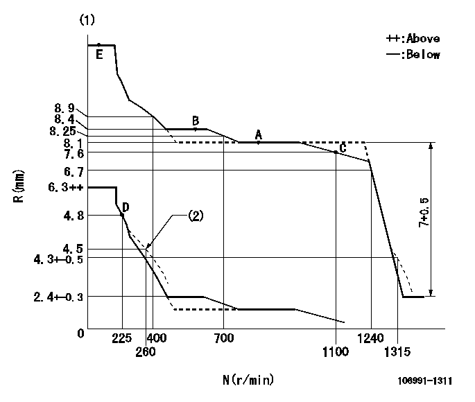
N:Pump speed
R:Rack position (mm)
(1)Tolerance for racks not indicated: +-0.05mm.
(2)Damper spring setting
----------
----------
----------
----------
Speed control lever angle

F:Full speed
----------
----------
a=6deg+-5deg
----------
----------
a=6deg+-5deg
0000000901

F:Full load
I:Idle
(1)Stopper bolt setting
----------
----------
a=10deg+-5deg b=32deg+-3deg
----------
----------
a=10deg+-5deg b=32deg+-3deg
Stop lever angle
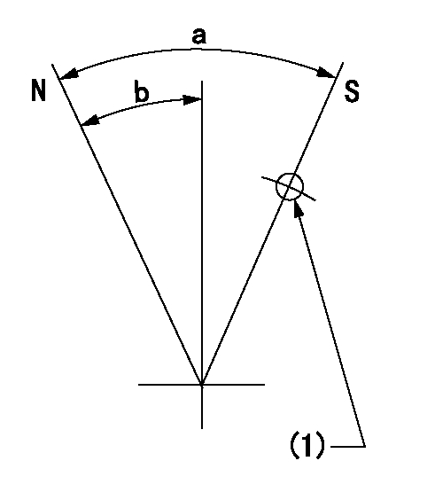
N:Pump normal
S:Stop the pump.
(1)Use the hole at R = aa
----------
aa=25mm
----------
a=64deg+-5deg b=51deg+-5deg
----------
aa=25mm
----------
a=64deg+-5deg b=51deg+-5deg
Timing setting

(1)Pump vertical direction
(2)Position of "Z" mark at the No 1 cylinder's beginning of injection (governor side)
(3)B.T.D.C.: aa (set timing)
(4)-
----------
aa=8deg
----------
a=(180deg)
----------
aa=8deg
----------
a=(180deg)
Information:
INSTALLING ENGINE TURNING TOOLBoth the inlet and exhaust valves will be closed on compression stroke. First check the bridge adjustment and then the valve lash adjustment. Bridge Adjustment
Check the bridge adjustment screw and locknut for tightness. If the adjusting screw and locknut are tight, proceed with the valve lash adjustment. If the bridge adjusting screw can be turned with a screwdriver without holding the locknut, the bridge requires adjustment. The bridge adjustment must be made before the valve lash is checked for proper clearance.Make bridge adjustment as follows:1. Back off adjusting screw several turns (counterclockwise) making sure it is not in contact with the valve stem.2. Firmly press straight down on the rocker arm above point of contact with bridge.
ADJUSTING BRIDGE3. Turn the adjusting screw clockwise until contact is made with the valve stem, then turn the adjusting screw an additional 30° or 1/12 turn (1/2 the distance between the two points on the locknut).4. Hold the adjusting screw in this position and tighten the locknut to 20 lb. ft. (27.2 N m).
TIGHTENING ADJUSTING SCREW LOCKNUTValve Lash Adjustment
To prevent possible injury, do not use the starter motor to turn the flywheel.Hot engine components can cause burns. Allow additional time for the engine to cool before measuring valve clearance.
Measure the valve lash with the engine stopped. To obtain an accurate measurement, allow at least 20 minutes for the valves to cool to cylinder head and block temperature.
If the valve clearance is within 0.08 mm (.003 in) of the nominal clearance given, adjustment is not required. If the clearance is not within these limits, set the clearance as given in the chart. After checking the bridge adjustment, make the valve lash adjustment.1. With No. 1 piston at TDC on compression, check valve lash between the bridge and rocker arm. See chart for cylinder and valve adjusting sequence.2. To adjust, loosen valve adjusting locknut and turn adjusting screw to allow feeler gauge to pass between top of bridge and the valve rocker arm. Set the inlet valve lash at .015" (0.38 mm) and exhaust valve lash at .030" (0.76 mm). 3. After proper adjustment, tighten the adjusting screw locknut to 22 lb. ft. (29.9 N m) and recheck lash clearance. 4. Turn flywheel 360° in direction of engine rotation. Align flywheel timing bolt with the timing hole in the flywheel. 3408-No. 6 Cylinder will be at TDC on compression stroke (all valves closed)3412-No. 11 Cylinder will be at TDC on compression stroke (all valves closed).5. Check lash and adjust as necessary on all remaining valves, see valve adjusting sequence chart.6. Tighten locknut and recheck lash clearance.7. Remove engine turning tool and install timing access cover, timing bolt and plug.Check Valve Rotation: After checking valve lash and before the valve covers are installed, check the valves for rotation.1. Mark a line on each valve retainer.2. Start the engine and run at low idle.3. Watch the line mark on each valve retainer. Each valve retainer should turn slightly each time the valve