Information injection-pump assembly
BOSCH
F 019 Z10 555
f019z10555
ZEXEL
106991-1310
1069911310
ISUZU
1156027640
1156027640
Rating:
Service parts 106991-1310 INJECTION-PUMP ASSEMBLY:
1.
_
6.
COUPLING PLATE
7.
COUPLING PLATE
8.
_
9.
_
11.
Nozzle and Holder
12.
Open Pre:MPa(Kqf/cm2)
15.7{160}/22.1{225}

15.
NOZZLE SET
Include in #1:
106991-1310
as INJECTION-PUMP ASSEMBLY
Cross reference number
BOSCH
F 019 Z10 555
f019z10555
ZEXEL
106991-1310
1069911310
ISUZU
1156027640
1156027640
Zexel num
Bosch num
Firm num
Name
Calibration Data:
Adjustment conditions
Test oil
1404 Test oil ISO4113 or {SAEJ967d}
1404 Test oil ISO4113 or {SAEJ967d}
Test oil temperature
degC
40
40
45
Nozzle and nozzle holder
105780-8140
Bosch type code
EF8511/9A
Nozzle
105780-0000
Bosch type code
DN12SD12T
Nozzle holder
105780-2080
Bosch type code
EF8511/9
Opening pressure
MPa
17.2
Opening pressure
kgf/cm2
175
Injection pipe
Outer diameter - inner diameter - length (mm) mm 8-3-600
Outer diameter - inner diameter - length (mm) mm 8-3-600
Overflow valve (drive side)
134424-4320
Overflow valve opening pressure (drive side)
kPa
255
221
289
Overflow valve opening pressure (drive side)
kgf/cm2
2.6
2.25
2.95
Overflow valve (governor side)
134424-2720
Overflow valve opening pressure (governor side)
kPa
255
221
289
Overflow valve opening pressure (governor side)
kgf/cm2
2.6
2.25
2.95
Tester oil delivery pressure
kPa
157
157
157
Tester oil delivery pressure
kgf/cm2
1.6
1.6
1.6
Direction of rotation (viewed from drive side)
Right R
Right R
Injection timing adjustment
Direction of rotation (viewed from drive side)
Right R
Right R
Injection order
1-8-7-6-
5-4-3-10
-9-2
Pre-stroke
mm
4.2
4.17
4.23
Rack position
Point A R=A
Point A R=A
Beginning of injection position
Governor side NO.1
Governor side NO.1
Difference between angles 1
Cal 1-8 deg. 27 26.75 27.25
Cal 1-8 deg. 27 26.75 27.25
Difference between angles 2
Cal 1-7 deg. 72 71.75 72.25
Cal 1-7 deg. 72 71.75 72.25
Difference between angles 3
Cal 1-6 deg. 99 98.75 99.25
Cal 1-6 deg. 99 98.75 99.25
Difference between angles 4
Cal 1-5 deg. 144 143.75 144.25
Cal 1-5 deg. 144 143.75 144.25
Difference between angles 5
Cal 1-4 deg. 171 170.75 171.25
Cal 1-4 deg. 171 170.75 171.25
Difference between angles 6
Cal 1-3 deg. 216 215.75 216.25
Cal 1-3 deg. 216 215.75 216.25
Difference between angles 7
Cal 1-10 deg. 243 242.75 243.25
Cal 1-10 deg. 243 242.75 243.25
Difference between angles 8
Cal 1-9 deg. 288 287.75 288.25
Cal 1-9 deg. 288 287.75 288.25
Difference between angles 9
Cyl.1-2 deg. 315 314.75 315.25
Cyl.1-2 deg. 315 314.75 315.25
Injection quantity adjustment
Adjusting point
A
Rack position
8.1
Pump speed
r/min
800
800
800
Average injection quantity
mm3/st.
104
102.5
105.5
Max. variation between cylinders
%
0
-2
2
Basic
*
Fixing the lever
*
Injection quantity adjustment_02
Adjusting point
B
Rack position
8.4
Pump speed
r/min
500
500
500
Average injection quantity
mm3/st.
104.1
102.1
106.1
Fixing the lever
*
Injection quantity adjustment_03
Adjusting point
C
Rack position
7.6
Pump speed
r/min
1100
1100
1100
Average injection quantity
mm3/st.
109.6
107.6
111.6
Fixing the lever
*
Injection quantity adjustment_04
Adjusting point
D
Rack position
4.8+-0.5
Pump speed
r/min
225
225
225
Average injection quantity
mm3/st.
8.7
7.4
10
Max. variation between cylinders
%
0
-13
13
Fixing the rack
*
Timer adjustment
Pump speed
r/min
600--
Advance angle
deg.
0
0
0
Remarks
Start
Start
Timer adjustment_02
Pump speed
r/min
550
Advance angle
deg.
0.3
Timer adjustment_03
Pump speed
r/min
820+-30
Advance angle
deg.
2
1.5
2.5
Timer adjustment_04
Pump speed
r/min
-
Advance angle
deg.
2
1.5
2.5
Remarks
Measure the actual speed.
Measure the actual speed.
Timer adjustment_05
Pump speed
r/min
1100
Advance angle
deg.
5.5
5
6
Remarks
Finish
Finish
Test data Ex:
Governor adjustment
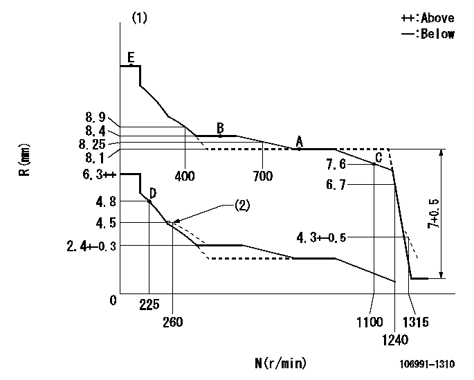
N:Pump speed
R:Rack position (mm)
(1)Tolerance for racks not indicated: +-0.05mm.
(2)Damper spring setting
----------
----------
----------
----------
Speed control lever angle

F:Full speed
----------
----------
a=6deg+-5deg
----------
----------
a=6deg+-5deg
0000000901
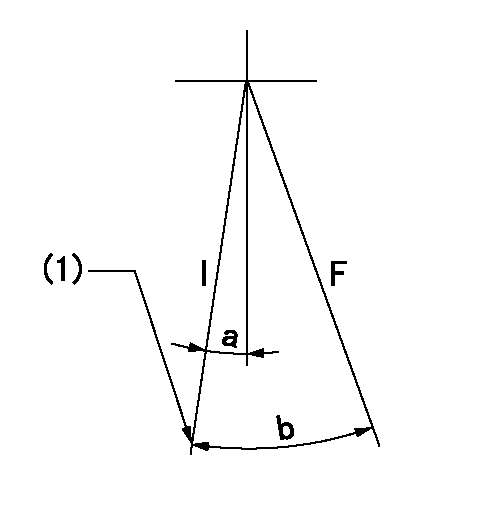
F:Full load
I:Idle
(1)Stopper bolt setting
----------
----------
a=10deg+-5deg b=32deg+-3deg
----------
----------
a=10deg+-5deg b=32deg+-3deg
Stop lever angle
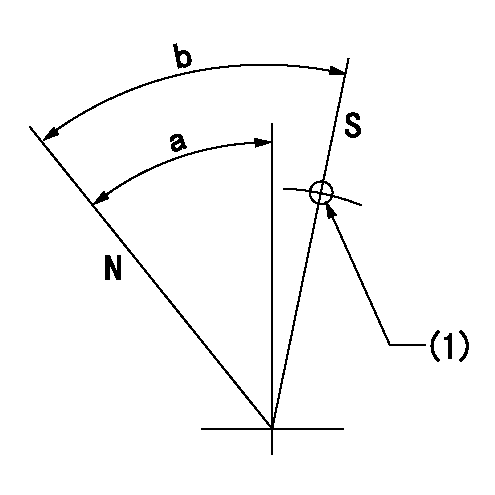
N:Pump normal
S:Stop the pump.
(1)Use the hole at R = aa
----------
aa=25mm
----------
a=51deg+-5deg b=64deg+-5deg
----------
aa=25mm
----------
a=51deg+-5deg b=64deg+-5deg
Timing setting

(1)Pump vertical direction
(2)Position of "Z" mark at the No 1 cylinder's beginning of injection (governor side)
(3)B.T.D.C.: aa (set timing)
(4)-
----------
aa=8deg
----------
a=(180deg)
----------
aa=8deg
----------
a=(180deg)
Information:
Final Fuel Filter
The filter element collects and holds contaminants and cannot be washed or otherwise restored.To remove the used filter, proceed as follows:1. Stop the engine and close the diesel fuel line valve (if equipped).2. Unscrew and remove filter. 3. Clean the gasket sealing surfaces on the filter bases. 4. Lubricate the new filter gasket with clean diesel fuel.
Do not pour fuel into the new filter element before installing. Prime the system as instructed in the topic, PRIMING THE FUEL SYSTEM.
5. Tighten the filter by hand until the gasket contacts the base, then tighten 1/2 to 3/4 turn more.6. Start the engine and run at 1000 rpm for several minutes and check for leaks. If the engine fails to start, prime the fuel system. See the topic TO PRIME THE SYSTEM. Keep New Fuel Filters On Hand
Extra filters should be kept on hand for replacement. Always keep filters wrapped in their original carton to insure against dust and dirt accumulation which will shorten the life of the filters or may cause damage to the fuel injection equipment.To Prime The System
If air is trapped in the fuel system, the diesel engine will either not start, or will misfire. Then it is necessary to prime the system.The fuel priming pump is mounted on the fuel filter base. If the fuel filter is changed or if the engine has run out of fuel, prime the fuel system as follows: 1. Be sure the fuel line valve is open and the engine shutoff control is off.2. Unlock the fuel priming pump.3. Operate priming pump until increased resistance is felt.4. Lock fuel priming pump.If the engine fails to start or continues to misfire or smoke, further bleeding is necessary. With engine running, or with the use of the priming pump, loosen fuel line nuts, one at a time, several times in succession and allow fuel to run until free of air bubbles. Tighten fuel line nuts.
LOOSENING FUEL INJECTION LINE TO BLEED SYSTEMFuel Injection Equipment
When improper fuel injection is affecting engine operation, a systematic check should be made to determine the cause. The most likely cause is dirt or water in the fuel. Drain the sediment from the fuel tank. Check the fuel pressure gauge as mentioned in the topic, FUEL FILTERING SYSTEM. Replace the filters if necessary. Then prime the fuel system until clean fuel reaches the fuel injection pumps. If the fuel system is air bound, priming the system will overcome the difficulty.If the engine is running irregularly, smoking, or knocking, a fuel injection valve may not be spraying the fuel properly.Direct Injection System
The fuel system of direct injection engines is essentially the same as precombustion chamber engines. The absence of the precombustion chamber requires a different fuel nozzle and adapter. Externally the direct injection fuel nozzle resembles the precombustion chamber nozzle except it is longer in length. Nozzle testing and replacement procedure is the same as illustrated for the precombustion chamber engines, except that an extracting tool is used to remove