Information injection-pump assembly
BOSCH
F 019 Z10 743
f019z10743
ZEXEL
106991-1265
1069911265
ISUZU
1156026655
1156026655
Rating:
Service parts 106991-1265 INJECTION-PUMP ASSEMBLY:
1.
_
6.
COUPLING PLATE
7.
COUPLING PLATE
8.
_
9.
_
11.
Nozzle and Holder
12.
Open Pre:MPa(Kqf/cm2)
15.7(160)/22.1(225)

15.
NOZZLE SET
Include in #1:
106991-1265
as INJECTION-PUMP ASSEMBLY
Cross reference number
BOSCH
F 019 Z10 743
f019z10743
ZEXEL
106991-1265
1069911265
ISUZU
1156026655
1156026655
Zexel num
Bosch num
Firm num
Name
F 019 Z10 743
1156026655 ISUZU
INJECTION-PUMP ASSEMBLY
10PD1-H * K 14CE PE10P PE
10PD1-H * K 14CE PE10P PE
Calibration Data:
Adjustment conditions
Test oil
1404 Test oil ISO4113 or {SAEJ967d}
1404 Test oil ISO4113 or {SAEJ967d}
Test oil temperature
degC
40
40
45
Nozzle and nozzle holder
105780-8140
Bosch type code
EF8511/9A
Nozzle
105780-0000
Bosch type code
DN12SD12T
Nozzle holder
105780-2080
Bosch type code
EF8511/9
Opening pressure
MPa
17.2
Opening pressure
kgf/cm2
175
Injection pipe
Outer diameter - inner diameter - length (mm) mm 8-3-600
Outer diameter - inner diameter - length (mm) mm 8-3-600
Overflow valve (drive side)
134424-4020
Overflow valve opening pressure (drive side)
kPa
255
255
255
Overflow valve opening pressure (drive side)
kgf/cm2
2.6
2.6
2.6
Overflow valve (governor side)
134424-2720
Overflow valve opening pressure (governor side)
kPa
255
255
255
Overflow valve opening pressure (governor side)
kgf/cm2
2.6
2.6
2.6
Tester oil delivery pressure
kPa
157
157
157
Tester oil delivery pressure
kgf/cm2
1.6
1.6
1.6
Direction of rotation (viewed from drive side)
Right R
Right R
Injection timing adjustment
Direction of rotation (viewed from drive side)
Right R
Right R
Injection order
1-8-7-6-
5-4-3-10
-9-2
Pre-stroke
mm
5.2
5.17
5.23
Rack position
Point A R=A
Point A R=A
Beginning of injection position
Governor side NO.1
Governor side NO.1
Difference between angles 1
Cal 1-8 deg. 27 26.75 27.25
Cal 1-8 deg. 27 26.75 27.25
Difference between angles 2
Cal 1-7 deg. 72 71.75 72.25
Cal 1-7 deg. 72 71.75 72.25
Difference between angles 3
Cal 1-6 deg. 99 98.75 99.25
Cal 1-6 deg. 99 98.75 99.25
Difference between angles 4
Cal 1-5 deg. 144 143.75 144.25
Cal 1-5 deg. 144 143.75 144.25
Difference between angles 5
Cal 1-4 deg. 171 170.75 171.25
Cal 1-4 deg. 171 170.75 171.25
Difference between angles 6
Cal 1-3 deg. 216 215.75 216.25
Cal 1-3 deg. 216 215.75 216.25
Difference between angles 7
Cal 1-10 deg. 243 242.75 243.25
Cal 1-10 deg. 243 242.75 243.25
Difference between angles 8
Cal 1-9 deg. 288 287.75 288.25
Cal 1-9 deg. 288 287.75 288.25
Difference between angles 9
Cyl.1-2 deg. 315 314.75 315.25
Cyl.1-2 deg. 315 314.75 315.25
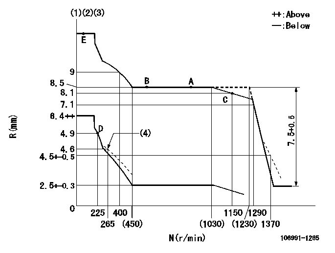
Injection quantity adjustment
Adjusting point
A
Rack position
8.5
Pump speed
r/min
800
800
800
Average injection quantity
mm3/st.
110.5
109
112
Max. variation between cylinders
%
0
-2
2
Basic
*
Fixing the lever
*
Injection quantity adjustment_02
Adjusting point
D
Rack position
4.9+-0.5
Pump speed
r/min
225
225
225
Average injection quantity
mm3/st.
8.6
6.6
10.6
Max. variation between cylinders
%
0
-13
13
Fixing the rack
*
Test data Ex:
Governor adjustment
N:Pump speed
R:Rack position (mm)
(1)Lever ratio: RT
(2)Target shim dimension: TH
(3)Tolerance for racks not indicated: +-0.05mm.
(4)Damper spring setting
----------
RT=0.8 TH=1.9mm
----------
----------
RT=0.8 TH=1.9mm
----------
Timer adjustment

(1)Adjusting range
(2)Step response time
(N): Speed of the pump
(L): Load
(theta) Advance angle
(Srd1) Step response time 1
(Srd2) Step response time 2
1. Adjusting conditions for the variable timer
(1)Adjust the clearance between the pickup and the protrusion to L.
----------
L=1-0.2mm N2=800r/min C2=(7)deg t1=1.5--sec. t2=1.5--sec.
----------
N1=1100++r/min P1=0kPa(0kgf/cm2) P2=392kPa(4kgf/cm2) C1=7+-0.3deg R01=0/4load R02=4/4load
----------
L=1-0.2mm N2=800r/min C2=(7)deg t1=1.5--sec. t2=1.5--sec.
----------
N1=1100++r/min P1=0kPa(0kgf/cm2) P2=392kPa(4kgf/cm2) C1=7+-0.3deg R01=0/4load R02=4/4load
Speed control lever angle

F:Full speed
----------
----------
a=7.5deg+-5deg
----------
----------
a=7.5deg+-5deg
0000000901

F:Full load
I:Idle
(1)Stopper bolt setting
----------
----------
a=10deg+-5deg b=32deg+-3deg
----------
----------
a=10deg+-5deg b=32deg+-3deg
Stop lever angle

N:Pump normal
S:Stop the pump.
----------
----------
a=60deg+-5deg b=73deg+-5deg
----------
----------
a=60deg+-5deg b=73deg+-5deg
0000001501 RACK SENSOR

V1:Supply voltage
V2f:Full side output voltage
V2i:Idle side output voltage
(A) Black
(B) Yellow
(C) Red
(D) Trimmer
(E): Shaft
(F) Nut
(G) Load lever
1. Load sensor adjustment
(1)Connect as shown in the above diagram and apply supply voltage V1.
(2)Hold the load lever (G) against the full side.
(3)Turn the shaft so that the voltage between (A) and (B) is V2.
(4)Hold the load lever (G) against the idle side.
(5)Adjust (D) so that the voltage between (A) and (B) is V2i.
(6)Repeat the above adjustments.
(7)Tighten the nut (F) at the point satisfying the standards.
(8)Hold the load lever against the full side stopper and the idle side stopper.
(9)At this time, confirm that the full side output voltage is V2f and the idle side output voltage is V2i.
----------
V1=5+-0.02V V2f=0.15+-0.03V V2i=2.35-0.03V
----------
----------
V1=5+-0.02V V2f=0.15+-0.03V V2i=2.35-0.03V
----------
Timing setting

(1)Pump vertical direction
(2)Position of "Z" mark at the No 1 cylinder's beginning of injection (governor side)
(3)B.T.D.C.: aa
(4)-
----------
aa=8deg
----------
a=(180deg)
----------
aa=8deg
----------
a=(180deg)
Information:
PARTS NEEDED
Qty
Part Number Description
1 4716029 MTG GP-INJECTOR (After Failure Only)
1 5548955 DEF SOFTWARE
1 ENGSOFTWARE ENGINE SOFTWARE
In order to allow equitable parts availability to all participating dealers, please limit your initial parts order to not exceed 25% of dealership population. This is an initial order recommendation only, and the ultimate responsibility for ordering the total number of parts needed to satisfy the program lies with the dealer.
ACTION REQUIRED
New DEF System software is available that reduces the risk of an internal DEF injector leak by improved temperature management. Please update the DEF system software at the next opportunity.
Ensure that all adjustments and repairs that are carried out to the Diesel Emission Fluid (DEF) system are performed by authorized personnel that have the correct training. Before beginning ANY work on the DEF system, refer to Operations and Maintenance Manual, "General Hazard" for safety information.
Before Failure:
Check that the engine software is the latest version before updating the DEF pump software.
If the engine software is not the latest version, update the Engine Software first.
If needed, update the engine software with the latest available in SIS WEB.
Flash the DEF Pump ECM with the software listed in the Parts Needed or latest available in SIS Web.
After Failure:
Ensure the appropriate steps have been followed when diagnosing a DEF injector failure. Refer to UENR0662.
If it is determined that replacement of DEF injector is required, refer to Disassembly and Assembly Manual - Diesel Fluid Injector - Remove and install.
After the DEF injector has been replaced, perform the DEF system software update as detailed in the "Before Failure" section above.
SERVICE CLAIM ALLOWANCES
Product smu/age whichever comes first Caterpillar Dealer Suggested Customer Suggested
Parts % Labor Hrs% Parts % Labor Hrs% Parts % Labor Hrs%
0-5000 hrs,
0-60 mo 100.0% 100.0% 0.0% 0.0% 0.0% 0.0%
This is a 0.5-hour job
An additional 1.5 hours is allowed for After failure.
PARTS DISPOSITION
Handle the parts in accordance with your Warranty Bulletin on warranty parts handling.