Information injection-pump assembly
ZEXEL
106991-1222
1069911222
ISUZU
1156026612
1156026612
Rating:
Service parts 106991-1222 INJECTION-PUMP ASSEMBLY:
1.
_
6.
COUPLING PLATE
7.
COUPLING PLATE
8.
_
9.
_
11.
Nozzle and Holder
1-15300-204-1
12.
Open Pre:MPa(Kqf/cm2)
15.7{160}/22.1{225}

15.
NOZZLE SET
Include in #1:
106991-1222
as INJECTION-PUMP ASSEMBLY
Cross reference number
ZEXEL
106991-1222
1069911222
ISUZU
1156026612
1156026612
Zexel num
Bosch num
Firm num
Name
Calibration Data:
Adjustment conditions
Test oil
1404 Test oil ISO4113 or {SAEJ967d}
1404 Test oil ISO4113 or {SAEJ967d}
Test oil temperature
degC
40
40
45
Nozzle and nozzle holder
105780-8140
Bosch type code
EF8511/9A
Nozzle
105780-0000
Bosch type code
DN12SD12T
Nozzle holder
105780-2080
Bosch type code
EF8511/9
Opening pressure
MPa
17.2
Opening pressure
kgf/cm2
175
Injection pipe
Outer diameter - inner diameter - length (mm) mm 8-3-600
Outer diameter - inner diameter - length (mm) mm 8-3-600
Overflow valve (drive side)
134424-4020
Overflow valve opening pressure (drive side)
kPa
255
221
289
Overflow valve opening pressure (drive side)
kgf/cm2
2.6
2.25
2.95
Overflow valve (governor side)
134424-2720
Overflow valve opening pressure (governor side)
kPa
255
221
289
Overflow valve opening pressure (governor side)
kgf/cm2
2.6
2.25
2.95
Tester oil delivery pressure
kPa
157
157
157
Tester oil delivery pressure
kgf/cm2
1.6
1.6
1.6
Direction of rotation (viewed from drive side)
Right R
Right R
Injection timing adjustment
Direction of rotation (viewed from drive side)
Right R
Right R
Injection order
1-8-7-6-
5-4-3-10
-9-2
Pre-stroke
mm
4.2
4.17
4.23
Rack position
Point A R=A
Point A R=A
Beginning of injection position
Governor side NO.1
Governor side NO.1
Difference between angles 1
Cal 1-8 deg. 27 26.75 27.25
Cal 1-8 deg. 27 26.75 27.25
Difference between angles 2
Cal 1-7 deg. 72 71.75 72.25
Cal 1-7 deg. 72 71.75 72.25
Difference between angles 3
Cal 1-6 deg. 99 98.75 99.25
Cal 1-6 deg. 99 98.75 99.25
Difference between angles 4
Cal 1-5 deg. 144 143.75 144.25
Cal 1-5 deg. 144 143.75 144.25
Difference between angles 5
Cal 1-4 deg. 171 170.75 171.25
Cal 1-4 deg. 171 170.75 171.25
Difference between angles 6
Cal 1-3 deg. 216 215.75 216.25
Cal 1-3 deg. 216 215.75 216.25
Difference between angles 7
Cal 1-10 deg. 243 242.75 243.25
Cal 1-10 deg. 243 242.75 243.25
Difference between angles 8
Cal 1-9 deg. 288 287.75 288.25
Cal 1-9 deg. 288 287.75 288.25
Difference between angles 9
Cyl.1-2 deg. 315 314.75 315.25
Cyl.1-2 deg. 315 314.75 315.25
Injection quantity adjustment
Adjusting point
A
Rack position
8.5
Pump speed
r/min
800
800
800
Average injection quantity
mm3/st.
110
108.5
111.5
Max. variation between cylinders
%
0
-2
2
Basic
*
Fixing the lever
*
Injection quantity adjustment_02
Adjusting point
B
Rack position
8.8
Pump speed
r/min
500
500
500
Average injection quantity
mm3/st.
111.6
109.6
113.6
Fixing the lever
*
Injection quantity adjustment_03
Adjusting point
C
Rack position
7.9
Pump speed
r/min
1150
1150
1150
Average injection quantity
mm3/st.
117.4
115.4
119.4
Fixing the lever
*
Injection quantity adjustment_04
Adjusting point
D
Rack position
4.9+-0.5
Pump speed
r/min
225
225
225
Average injection quantity
mm3/st.
8.8
7.5
10.1
Max. variation between cylinders
%
0
-13
13
Fixing the rack
*
Timer adjustment
Pump speed
r/min
600--
Advance angle
deg.
0
0
0
Load
4/4
Remarks
Start
Start
Timer adjustment_02
Pump speed
r/min
550
Advance angle
deg.
0.3
Load
4/4
Timer adjustment_03
Pump speed
r/min
800+-30
Advance angle
deg.
2
1.5
2.5
Load
4/4
Timer adjustment_04
Pump speed
r/min
900
Advance angle
deg.
2
1.5
2.5
Load
3/4
Timer adjustment_05
Pump speed
r/min
1150
Advance angle
deg.
5.5
5
6
Load
4/4
Remarks
Finish
Finish
Test data Ex:
Governor adjustment
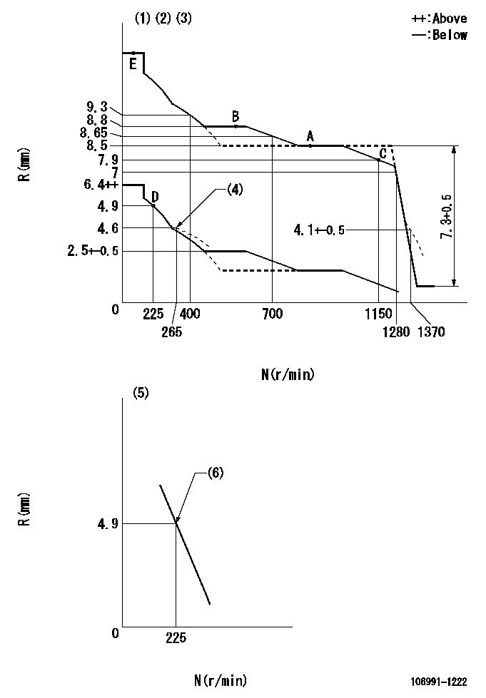
N:Pump speed
R:Rack position (mm)
(1)Lever ratio: RT
(2)Target shim dimension: TH
(3)Tolerance for racks not indicated: +-0.05mm.
(4)Damper spring setting
(5)Variable speed specification: idling adjustment
(6)Main spring setting
----------
RT=0.8 TH=2mm
----------
----------
RT=0.8 TH=2mm
----------
Speed control lever angle
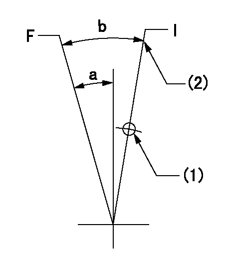
F:Full speed
I:Idle
(1)Use the hole at R = aa
(2)Stopper bolt setting
----------
aa=150mm
----------
a=7deg+-5deg b=(15deg)+-5deg
----------
aa=150mm
----------
a=7deg+-5deg b=(15deg)+-5deg
0000000901

F:Full load
I:Idle
(1)Stopper bolt setting
(2)Use the hole at R = aa
----------
aa=35mm
----------
a=10deg+-5deg b=34deg+-3deg
----------
aa=35mm
----------
a=10deg+-5deg b=34deg+-3deg
Stop lever angle

N:Pump normal
S:Stop the pump.
----------
----------
a=60deg+-5deg b=73deg+-5deg
----------
----------
a=60deg+-5deg b=73deg+-5deg
0000001201
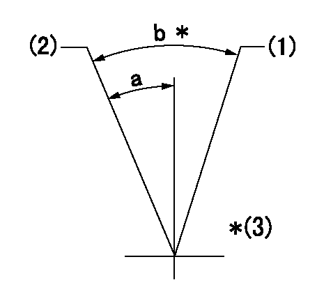
(1)Variable speed specification
(2)Minimum - maximum speed specification
(3)Lever angle = c or less
----------
----------
a=13deg+-5deg b=(20deg) c=26deg
----------
----------
a=13deg+-5deg b=(20deg) c=26deg
0000001501 LEVER
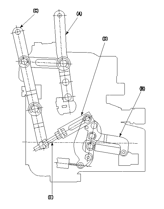
2-stage changeover lever adjustment
(A) Speed lever
(B) Load lever
(C) 2-stage changeover lever
(D) Link
(E) Bolt
1. Minimum-maximum speed specification adjustment (when running)
(1)After completing governor adjustment, hold the 2-stage changeover lever (C) so that the speed lever (A) contacts the full speed stopper.
(2)In this condition, the load lever is held in the idle position.
(3)Adjust bolt (E) so that the clearance between the pin underneath lever (C) and the end of the long groove in link (D) is L.
(4)Lock using the nut.
2. Variable speed specification adjustment (at operation)
(1)Hold the 2-stage changeover lever (C) so that the load lever (B) contacts the full load stopper. (When the load lever is equipped with a cancel mechanism, move it so that it contacts the stopper without canceling.)
(2)In this condition, confirm that the speed lever (A) moves from idle to full speed.
----------
L=1~2mm
----------
----------
L=1~2mm
----------
Timing setting

(1)Pump vertical direction
(2)Position of "Z" mark at the No 1 cylinder's beginning of injection (governor side)
(3)B.T.D.C.: aa (set timing)
(4)-
----------
aa=8deg
----------
a=(180deg)
----------
aa=8deg
----------
a=(180deg)
Information:
1. Disconnect electrical plug (1) and throttle linkage (2).2. Disconnect six fuel lines (3) from injection pump. 3. Remove inspection plate (5) from the timing gear cover. 4. Make an alingment of the timing marks on fuel injection pump gear (7) and idler gear (6), or put identification marks on the gears for correct installation. 5. Remove three bolts (8) that hold the fuel injection pump drive gear to the fuel injection pump.
Typical Example6. Put alignment marks on the fuel injection pump and the timing gear case cover as shown. Remove three nuts (9) and washers that hold the fuel injection pump in place. Remove fuel injection pump (10). Remove the gasket from the timing gear case. The following steps are for the installation of the fuel injection pump.7. Put the gasket for fuel injection pump (10) in position on the timing gear case. 8. Position the fuel injection pump; be sure dowel (11) in fuel injection pump gear (7) is in alignment with the groove (slot) in the fuel injection pump shaft when the fuel injection pump is put in position.
Typical Example9. For initial fuel injection pump timing, make an alignment of the reference marks on the fuel injection pump and the timing gear case. Install the three nuts (9) and washers that hold fuel injection pump (10) in place. 10. Be sure the timing marks or the marks that were put on the fuel injection pump gear and idler gear are in alignment. Install three bolts (8) that hold the fuel injection pump gear to the fuel injection pump. 11. Install plate (5) with a new gasket.12 Connect all fuel lines (3), control linkage (2) and electrical plug (1).13. Prime the fuel system. See the MAINTENANCE MANUAL.