Information injection-pump assembly
ZEXEL
106991-1102
1069911102
ISUZU
1156025312
1156025312
Rating:
Service parts 106991-1102 INJECTION-PUMP ASSEMBLY:
1.
_
6.
COUPLING PLATE
7.
COUPLING PLATE
8.
_
9.
_
11.
Nozzle and Holder
1-15300-204-1
12.
Open Pre:MPa(Kqf/cm2)
15.7{160}/22.1{225}

15.
NOZZLE SET
Include in #1:
106991-1102
as INJECTION-PUMP ASSEMBLY
Cross reference number
ZEXEL
106991-1102
1069911102
ISUZU
1156025312
1156025312
Zexel num
Bosch num
Firm num
Name
Calibration Data:
Adjustment conditions
Test oil
1404 Test oil ISO4113 or {SAEJ967d}
1404 Test oil ISO4113 or {SAEJ967d}
Test oil temperature
degC
40
40
45
Nozzle and nozzle holder
105780-8140
Bosch type code
EF8511/9A
Nozzle
105780-0000
Bosch type code
DN12SD12T
Nozzle holder
105780-2080
Bosch type code
EF8511/9
Opening pressure
MPa
17.2
Opening pressure
kgf/cm2
175
Injection pipe
Outer diameter - inner diameter - length (mm) mm 8-3-600
Outer diameter - inner diameter - length (mm) mm 8-3-600
Overflow valve (drive side)
134424-4020
Overflow valve opening pressure (drive side)
kPa
255
221
289
Overflow valve opening pressure (drive side)
kgf/cm2
2.6
2.25
2.95
Overflow valve (governor side)
134424-4020
Overflow valve opening pressure (governor side)
kPa
255
221
289
Overflow valve opening pressure (governor side)
kgf/cm2
2.6
2.25
2.95
Tester oil delivery pressure
kPa
157
157
157
Tester oil delivery pressure
kgf/cm2
1.6
1.6
1.6
Direction of rotation (viewed from drive side)
Right R
Right R
Injection timing adjustment
Direction of rotation (viewed from drive side)
Right R
Right R
Injection order
1-4-9-8-
5-2-11-1
0-3-6-7-
Pre-stroke
mm
4.2
4.17
4.23
Rack position
Point A R=A
Point A R=A
Beginning of injection position
Governor side NO.1
Governor side NO.1
Difference between angles 1
Cal 1-4 deg. 15 14.75 15.25
Cal 1-4 deg. 15 14.75 15.25
Difference between angles 2
Cal 1-9 deg. 60 59.75 60.25
Cal 1-9 deg. 60 59.75 60.25
Difference between angles 3
Cal 1-8 deg. 75 74.75 75.25
Cal 1-8 deg. 75 74.75 75.25
Difference between angles 4
Cal 1-5 deg. 120 119.75 120.25
Cal 1-5 deg. 120 119.75 120.25
Difference between angles 5
Cyl.1-2 deg. 135 134.75 135.25
Cyl.1-2 deg. 135 134.75 135.25
Difference between angles 6
Cal 1-11 deg. 180 179.75 180.25
Cal 1-11 deg. 180 179.75 180.25
Difference between angles 7
Cal 1-10 deg. 195 194.75 195.25
Cal 1-10 deg. 195 194.75 195.25
Difference between angles 8
Cal 1-3 deg. 240 239.75 240.25
Cal 1-3 deg. 240 239.75 240.25
Difference between angles 9
Cal 1-6 deg. 255 254.75 255.25
Cal 1-6 deg. 255 254.75 255.25
Difference between angles 10
Cal 1-7 deg. 300 299.75 300.25
Cal 1-7 deg. 300 299.75 300.25
Difference between angles 11
Cal 1-12 deg. 315 314.75 315.25
Cal 1-12 deg. 315 314.75 315.25
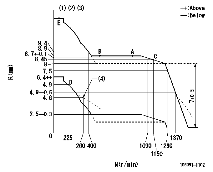
Injection quantity adjustment
Adjusting point
A
Rack position
8.9
Pump speed
r/min
800
800
800
Average injection quantity
mm3/st.
112
110.5
113.5
Max. variation between cylinders
%
0
-2
2
Basic
*
Fixing the lever
*
Injection quantity adjustment_02
Adjusting point
C
Rack position
8.45
Pump speed
r/min
1150
1150
1150
Average injection quantity
mm3/st.
123.7
121.7
125.7
Fixing the lever
*
Injection quantity adjustment_03
Adjusting point
D
Rack position
4.9+-0.5
Pump speed
r/min
225
225
225
Average injection quantity
mm3/st.
8.8
6.8
10.8
Max. variation between cylinders
%
0
-13
13
Fixing the rack
*
Test data Ex:
Governor adjustment
N:Pump speed
R:Rack position (mm)
(1)Lever ratio: RT
(2)Target shim dimension: TH
(3)Tolerance for racks not indicated: +-0.05mm.
(4)Damper spring setting
----------
RT=0.8 TH=2.1mm
----------
----------
RT=0.8 TH=2.1mm
----------
Timer adjustment

(1)Adjusting range
(2)Step response time
(N): Speed of the pump
(L): Load
(theta) Advance angle
(Srd1) Step response time 1
(Srd2) Step response time 2
1. Adjusting conditions for the variable timer
(1)Adjust the clearance between the pickup and the protrusion to L.
----------
L=1-0.2mm N2=800r/min C2=(7)deg t1=1.5--sec. t2=1.5--sec.
----------
N1=1100++r/min P1=0kPa(0kgf/cm2) P2=392kPa(4kgf/cm2) C1=7+-0.3deg R01=0/4load R02=4/4load
----------
L=1-0.2mm N2=800r/min C2=(7)deg t1=1.5--sec. t2=1.5--sec.
----------
N1=1100++r/min P1=0kPa(0kgf/cm2) P2=392kPa(4kgf/cm2) C1=7+-0.3deg R01=0/4load R02=4/4load
Speed control lever angle

F:Full speed
----------
----------
a=7deg+-5deg
----------
----------
a=7deg+-5deg
0000000901

F:Full load
I:Idle
(1)Stopper bolt setting
----------
----------
a=10deg+-5deg b=34.5deg+-3deg
----------
----------
a=10deg+-5deg b=34.5deg+-3deg
Stop lever angle

N:Pump normal
S:Stop the pump.
----------
----------
a=60deg+-5deg b=73deg+-5deg
----------
----------
a=60deg+-5deg b=73deg+-5deg
0000001501 RACK SENSOR

V1:Supply voltage
V2f:Full side output voltage
V2i:Idle side output voltage
(A) Black
(B) Yellow
(C) Red
(D) Trimmer
(E): Shaft
(F) Nut
(G) Load lever
1. Load sensor adjustment
(1)Connect as shown in the above diagram and apply supply voltage V1.
(2)Hold the load lever (G) against the full side.
(3)Turn the shaft so that the voltage between (A) and (B) is V2.
(4)Hold the load lever (G) against the idle side.
(5)Adjust (D) so that the voltage between (A) and (B) is V2i.
(6)Repeat the above adjustments.
(7)Tighten the nut (F) at the point satisfying the standards.
(8)Hold the load lever against the full side stopper and the idle side stopper.
(9)At this time, confirm that the full side output voltage is V2f and the idle side output voltage is V2i.
----------
V1=5+-0.02V V2f=0.15+0.03V V2i=2.35-0.03V
----------
----------
V1=5+-0.02V V2f=0.15+0.03V V2i=2.35-0.03V
----------
Timing setting

(1)Pump vertical direction
(2)Position of "Z" mark at the No 1 cylinder's beginning of injection (governor side)
(3)B.T.D.C.: aa (set timing)
(4)-
----------
aa=8deg
----------
a=(180deg)
----------
aa=8deg
----------
a=(180deg)
Information:
October 20, 2001
U-280
A-192
AU-181
S-134
H-97
O-211
Priority PRODUCT IMPROVEMENT PROGRAM FOR TIGHTENING THE INJECTOR ARM JAM NUTS ON CERTAIN D350E II ARTICULATED TRUCKS AND ON CERTAIN D400E II EJECTOR AND D400E II ARTICULATED TRUCKS
1123 1290 PI30241 This Program must be administered as soon as possible. When reporting the repair, use "PI30241" as the Part number and "7751" as the Group Number, "56" as the Warranty Claim Description Code and "T" as the SIMS Description Code. Exception: If the repair is done after failure, use "PI30241" as the Part Number, "7751" as the Group Number, "96" as the Warranty Claim Description Code, and "Z" as the SIMS Description Code.
The information supplied in this service letter may not be valid after the termination date of this program. Do not perform the work outlined in this Service Letter after the termination date without first contacting your Caterpillar product analyst.
COMPLETION DATE
TERMINATION DATE
April 30, 2002 October 31, 2002PROBLEM
The Injector rocker arm jam nuts on some D350E II Articulated, D400E II Ejector and D400E II Articulated Trucks are coming loose.
AFFECTED PRODUCT
Model Identification Number
D350E II ARTICULATED 2XW1-473, 476
D400 II EJECTOR APF1-324, 327
D400E II ARTICULATED 8PS1-1034, 1036-1040, 1044, 1050-1053, 1055PARTS NEEDED
None Needed
ACTION REQUIRED
See the attached Rework Procedure.
OWNER NOTIFICATION
U.S. and Canadian owners will receive the attached Owner Notification.
SERVICE CLAIM ALLOWANCES
Caterpillar Dealer Suggested Customer Suggested
Parts Labor Hrs. Parts Labor Hrs. Parts Labor Hrs.
100% * 0 0 0 0
* 1.0-hr is allowed to Remove and Install valve covers and torque the injector arm jam nuts. Six minutes are allowed to adjust each Unit Injector if needed ? up to a maximum of .6-hrs is allowed to adjust all six.
U.S. and Canadian Dealers Only - Eligible dealers may enter a Type 2 SIMS ReportAttach. (1-Owner Notification)
(2-Rework Procedure)
COPY OF OWNER NOTIFICATION FOR U.S. AND CANADIAN OWNERS
XYZ Corporation
3240 Arrow Drive
Anywhere, YZ 99999
PRIORITY - TIGHTENING THE INJECTOR ARM JAM NUTS
MODELS INVOLVED - CERTAIN D350E II ARTICULATED TRUCKS AND ON CERTAIN D400E II EJECTOR AND D400E II ARTICULATED TRUCKS
Dear Caterpillar Product Owner:
The Injector rocker arm jam nuts on some D350E II Articulated Trucks, D400E II Ejector and D400E II Articulated Trucks need to be inspected. The injector arm jam nuts may need to be tightened on the products listed below. You will not be charged for the service performed.
Contact your local Caterpillar dealer immediately to schedule this service. The dealer will advise you of the time required to complete this service. Please refer the dealer to their Service Letter dated October 20, 2001 when scheduling this service.
We regret the inconvenience this may cause you, but urge you to have this service performed as soon as possible to prevent unscheduled downtime.
Caterpillar Inc.
Identification #(s)
Attached to October 20, 2001 Service Letter
Rework Procedure
NOTE This service letter does not need to be performed if Injector jam nuts have already been torqued to the higher spec during routine valve lash/unit injector adjustment as described in Service Magazine article SEPD0581(2001/06/04).
Remove the valve covers.
Place a flat head screwdriver in the injector adjusting screw and see if it will turn.
If the screw turns then the unit injector needs to be adjusted.(See step 5)
If the screw will NOT turn, mark a line across the screw, nut, and injector arm