Information injection-pump assembly
ZEXEL
106991-1032
1069911032
ISUZU
1156021882
1156021882
Rating:
Service parts 106991-1032 INJECTION-PUMP ASSEMBLY:
1.
_
6.
COUPLING PLATE
7.
COUPLING PLATE
8.
_
9.
_
11.
Nozzle and Holder
1-15300-204-1
12.
Open Pre:MPa(Kqf/cm2)
15.7{160}/22.1{225}

15.
NOZZLE SET
Include in #1:
106991-1032
as INJECTION-PUMP ASSEMBLY
Cross reference number
ZEXEL
106991-1032
1069911032
ISUZU
1156021882
1156021882
Zexel num
Bosch num
Firm num
Name
Calibration Data:
Adjustment conditions
Test oil
1404 Test oil ISO4113 or {SAEJ967d}
1404 Test oil ISO4113 or {SAEJ967d}
Test oil temperature
degC
40
40
45
Nozzle and nozzle holder
105780-8140
Bosch type code
EF8511/9A
Nozzle
105780-0000
Bosch type code
DN12SD12T
Nozzle holder
105780-2080
Bosch type code
EF8511/9
Opening pressure
MPa
17.2
Opening pressure
kgf/cm2
175
Injection pipe
Outer diameter - inner diameter - length (mm) mm 8-3-600
Outer diameter - inner diameter - length (mm) mm 8-3-600
Overflow valve (drive side)
134424-4020
Overflow valve opening pressure (drive side)
kPa
255
221
289
Overflow valve opening pressure (drive side)
kgf/cm2
2.6
2.25
2.95
Overflow valve (governor side)
134424-2720
Overflow valve opening pressure (governor side)
kPa
255
221
289
Overflow valve opening pressure (governor side)
kgf/cm2
2.6
2.25
2.95
Tester oil delivery pressure
kPa
157
157
157
Tester oil delivery pressure
kgf/cm2
1.6
1.6
1.6
Direction of rotation (viewed from drive side)
Right R
Right R
Injection timing adjustment
Direction of rotation (viewed from drive side)
Right R
Right R
Injection order
1-8-7-6-
5-4-3-10
-9-2
Pre-stroke
mm
4.2
4.17
4.23
Rack position
Point A R=A
Point A R=A
Beginning of injection position
Governor side NO.1
Governor side NO.1
Difference between angles 1
Cal 1-8 deg. 27 26.75 27.25
Cal 1-8 deg. 27 26.75 27.25
Difference between angles 2
Cal 1-7 deg. 72 71.75 72.25
Cal 1-7 deg. 72 71.75 72.25
Difference between angles 3
Cal 1-6 deg. 99 98.75 99.25
Cal 1-6 deg. 99 98.75 99.25
Difference between angles 4
Cal 1-5 deg. 144 143.75 144.25
Cal 1-5 deg. 144 143.75 144.25
Difference between angles 5
Cal 1-4 deg. 171 170.75 171.25
Cal 1-4 deg. 171 170.75 171.25
Difference between angles 6
Cal 1-3 deg. 216 215.75 216.25
Cal 1-3 deg. 216 215.75 216.25
Difference between angles 7
Cal 1-10 deg. 243 242.75 243.25
Cal 1-10 deg. 243 242.75 243.25
Difference between angles 8
Cal 1-9 deg. 288 287.75 288.25
Cal 1-9 deg. 288 287.75 288.25
Difference between angles 9
Cyl.1-2 deg. 315 314.75 315.25
Cyl.1-2 deg. 315 314.75 315.25
Injection quantity adjustment
Adjusting point
A
Rack position
8.5
Pump speed
r/min
800
800
800
Average injection quantity
mm3/st.
110
108.5
111.5
Max. variation between cylinders
%
0
-2
2
Basic
*
Fixing the lever
*
Injection quantity adjustment_02
Adjusting point
B
Rack position
8.8
Pump speed
r/min
500
500
500
Average injection quantity
mm3/st.
111.6
109.6
113.6
Fixing the lever
*
Injection quantity adjustment_03
Adjusting point
C
Rack position
7.9
Pump speed
r/min
1150
1150
1150
Average injection quantity
mm3/st.
117.4
115.4
119.4
Fixing the lever
*
Injection quantity adjustment_04
Adjusting point
D
Rack position
4.9+-0.5
Pump speed
r/min
225
225
225
Average injection quantity
mm3/st.
8.8
7.5
10.1
Max. variation between cylinders
%
0
-13
13
Fixing the rack
*
Test data Ex:
Governor adjustment
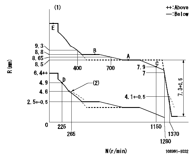
N:Pump speed
R:Rack position (mm)
(1)Tolerance for racks not indicated: +-0.05mm.
(2)Damper spring setting
----------
----------
----------
----------
Timer adjustment

(1)Adjusting range
(2)Step response time
(N): Speed of the pump
(L): Load
(theta) Advance angle
(Srd1) Step response time 1
(Srd2) Step response time 2
1. Adjusting conditions for the variable timer
(1)Adjust the clearance between the pickup and the protrusion to L.
----------
L=1-0.2mm N2=800r/min C2=(7)deg t1=1.5--sec. t2=1.5--sec.
----------
N1=1100++r/min P1=0kPa(0kgf/cm2) P2=392kPa(4kgf/cm2) C1=7+-0.3deg R01=0/4load R02=4/4load
----------
L=1-0.2mm N2=800r/min C2=(7)deg t1=1.5--sec. t2=1.5--sec.
----------
N1=1100++r/min P1=0kPa(0kgf/cm2) P2=392kPa(4kgf/cm2) C1=7+-0.3deg R01=0/4load R02=4/4load
Speed control lever angle

F:Full speed
----------
----------
a=7deg+-5deg
----------
----------
a=7deg+-5deg
0000000901
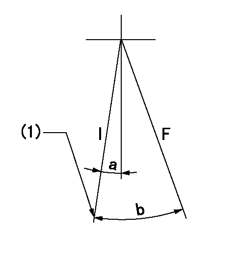
F:Full load
I:Idle
(1)Stopper bolt setting
----------
----------
a=10deg+-5deg b=34deg+-3deg
----------
----------
a=10deg+-5deg b=34deg+-3deg
Stop lever angle

N:Pump normal
S:Stop the pump.
----------
----------
a=60deg+-5deg b=73deg+-5deg
----------
----------
a=60deg+-5deg b=73deg+-5deg
0000001501 RACK SENSOR

V1:Supply voltage
V2f:Full side output voltage
V2i:Idle side output voltage
(A) Black
(B) Yellow
(C) Red
(D) Trimmer
(E): Shaft
(F) Nut
(G) Load lever
1. Load sensor adjustment
(1)Connect as shown in the above diagram and apply supply voltage V1.
(2)Hold the load lever (G) against the full side.
(3)Turn the shaft so that the voltage between (A) and (B) is V2.
(4)Hold the load lever (G) against the idle side.
(5)Adjust (D) so that the voltage between (A) and (B) is V2i.
(6)Repeat the above adjustments.
(7)Tighten the nut (F) at the point satisfying the standards.
(8)Hold the load lever against the full side stopper and the idle side stopper.
(9)At this time, confirm that the full side output voltage is V2f and the idle side output voltage is V2i.
----------
V1=5+-0.02V V2f=0.15+0.03V V2i=2.35-0.03V
----------
----------
V1=5+-0.02V V2f=0.15+0.03V V2i=2.35-0.03V
----------
Timing setting

(1)Pump vertical direction
(2)Position of "Z" mark at the No 1 cylinder's beginning of injection (governor side)
(3)B.T.D.C.: aa (set timing)
(4)-
----------
aa=8deg
----------
a=(180deg)
----------
aa=8deg
----------
a=(180deg)
Information:
Caterpillar: Confidential Yellow
PSP FOR INSTALLATION OF NEW INTERNAL FUEL INJECTION LINES ON CERTAIN 992C LOADERS; 773B TRUCKS; D9L, 651E, 657E, 772B TRA CTORS - MAILED US AND CANADA, CACO, COSA, LIMITED BRAZIL
The information supplied in this service letter may not be valid after the termination date of this program. Do not perform the work outlined in this Service Letter after the termination date without first contacting your Caterpillar product analyst.
PRODUCT SUPPORT PROGRAM FOR INSTALLATION OF NEW INTERNAL FUEL INJECTION LINES ON CERTAIN 992C LOADERS; 773B TRUCKS; D9L, 651E, 657E, 772B TRACTORS, 1252, PS4094 U-116 A-52 C-112 B-10.1 O-84 This Program can be administered either before or after a failure. In either case the decision whether to apply the Program is made by the dealer. When reporting the repair, use "PS4094" as Part Number and "7755" as Group Number. Although products in the field are to be administered as described above, dealers should purge parts stock immediately. Termination Date
November 30, 1987
Problem
There have been some failures of the 2W8142 Line As. (internal fuel lines - under the valve cover) on the Affected Product. These failures have been cracks in the fuel lines which can result in poor engine performance and dilution of the engine oil with fuel. New fuel lines are now used in production.
Affected Product
Model Identification Number D9L 14Y2971, 3023-3039, 3041-3046, 3048-3139, 3141-3569, 3571-3609, 3611-3661, 3663-3675, 3677-3686, 3688-3697, 3699-3701, 3705-3707, 3709-3730, 3732-3775, 3777-3960, 3962-3966, 3974-3976, 3983 651E 89Z109 - 113, 116-142 657E 90Z127 - 133, 135-173 91Z217 - 282 772B 64W172, 173 773B 63W1443, 1462, 1464-1489, 1491-1827, 1831, 1836, 1842, 1843 992C 49Z622, 623, 626-628, 630, 634, 636, 638, 639, 641-643, 645-649, 651-765, 767-771, 773-819, 821-939, 944
Parts Needed
12 - 7C5570 Line As. Use as needed. If one or more 7C5570 Line As. have already been installed, they should not be replaced. Only replace the 2W8142 Line Assemblies.
Action Required
Parts Stock Remove all 2W8142 Line Assemblies from parts stock. Affected Product All 2W8142 Line Assemblies on an engine should be replaced at the same time. Install the new parts according to the procedures in the appropriate Service Manuals. WARRANTY ALLOWANCES Parts Stock Submit one claim for all 2W8142 Line Assemblies that are removed from parts stock. (SEE ILLUSTRATION)
Parts Disposition
Handle the parts in accordance with your Warranty Bulletin on warranty parts handling.