Information injection-pump assembly
ZEXEL
106991-1012
1069911012
ISUZU
1156024982
1156024982
Rating:
Cross reference number
ZEXEL
106991-1012
1069911012
ISUZU
1156024982
1156024982
Zexel num
Bosch num
Firm num
Name
Calibration Data:
Adjustment conditions
Test oil
1404 Test oil ISO4113 or {SAEJ967d}
1404 Test oil ISO4113 or {SAEJ967d}
Test oil temperature
degC
40
40
45
Nozzle and nozzle holder
105780-8140
Bosch type code
EF8511/9A
Nozzle
105780-0000
Bosch type code
DN12SD12T
Nozzle holder
105780-2080
Bosch type code
EF8511/9
Opening pressure
MPa
17.2
Opening pressure
kgf/cm2
175
Injection pipe
Outer diameter - inner diameter - length (mm) mm 8-3-600
Outer diameter - inner diameter - length (mm) mm 8-3-600
Overflow valve (drive side)
134424-4020
Overflow valve opening pressure (drive side)
kPa
255
221
289
Overflow valve opening pressure (drive side)
kgf/cm2
2.6
2.25
2.95
Overflow valve (governor side)
134424-2720
Overflow valve opening pressure (governor side)
kPa
255
221
289
Overflow valve opening pressure (governor side)
kgf/cm2
2.6
2.25
2.95
Tester oil delivery pressure
kPa
157
157
157
Tester oil delivery pressure
kgf/cm2
1.6
1.6
1.6
Direction of rotation (viewed from drive side)
Right R
Right R
Injection timing adjustment
Direction of rotation (viewed from drive side)
Right R
Right R
Injection order
1-8-7-6-
5-4-3-10
-9-2
Pre-stroke
mm
4.2
4.17
4.23
Rack position
Point A R=A
Point A R=A
Beginning of injection position
Governor side NO.1
Governor side NO.1
Difference between angles 1
Cal 1-8 deg. 27 26.75 27.25
Cal 1-8 deg. 27 26.75 27.25
Difference between angles 2
Cal 1-7 deg. 72 71.75 72.25
Cal 1-7 deg. 72 71.75 72.25
Difference between angles 3
Cal 1-6 deg. 99 98.75 99.25
Cal 1-6 deg. 99 98.75 99.25
Difference between angles 4
Cal 1-5 deg. 144 143.75 144.25
Cal 1-5 deg. 144 143.75 144.25
Difference between angles 5
Cal 1-4 deg. 171 170.75 171.25
Cal 1-4 deg. 171 170.75 171.25
Difference between angles 6
Cal 1-3 deg. 216 215.75 216.25
Cal 1-3 deg. 216 215.75 216.25
Difference between angles 7
Cal 1-10 deg. 243 242.75 243.25
Cal 1-10 deg. 243 242.75 243.25
Difference between angles 8
Cal 1-9 deg. 288 287.75 288.25
Cal 1-9 deg. 288 287.75 288.25
Difference between angles 9
Cyl.1-2 deg. 315 314.75 315.25
Cyl.1-2 deg. 315 314.75 315.25
Injection quantity adjustment
Adjusting point
A
Rack position
8.1
Pump speed
r/min
800
800
800
Average injection quantity
mm3/st.
104
102.5
105.5
Max. variation between cylinders
%
0
-2
2
Basic
*
Fixing the lever
*
Injection quantity adjustment_02
Adjusting point
B
Rack position
8.4
Pump speed
r/min
500
500
500
Average injection quantity
mm3/st.
104.1
102.1
106.1
Fixing the lever
*
Injection quantity adjustment_03
Adjusting point
C
Rack position
7.6
Pump speed
r/min
1100
1100
1100
Average injection quantity
mm3/st.
109.6
107.6
111.6
Fixing the lever
*
Injection quantity adjustment_04
Adjusting point
D
Rack position
4.8+-0.5
Pump speed
r/min
225
225
225
Average injection quantity
mm3/st.
8.7
7.4
10
Max. variation between cylinders
%
0
-13
13
Fixing the rack
*
Timer adjustment
Pump speed
r/min
600--
Advance angle
deg.
0
0
0
Load
4/4
Remarks
Start
Start
Timer adjustment_02
Pump speed
r/min
550
Advance angle
deg.
0.3
Load
4/4
Timer adjustment_03
Pump speed
r/min
820+-30
Advance angle
deg.
2
1.5
2.5
Load
4/4
Timer adjustment_04
Pump speed
r/min
900
Advance angle
deg.
2
1.5
2.5
Load
3/4
Timer adjustment_05
Pump speed
r/min
1100
Advance angle
deg.
5.5
5
6
Load
4/4
Remarks
Finish
Finish
Test data Ex:
Governor adjustment
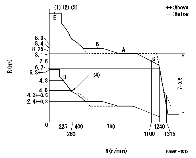
N:Pump speed
R:Rack position (mm)
(1)Lever ratio: RT
(2)Target shim dimension: TH
(3)Tolerance for racks not indicated: +-0.05mm.
(4)Damper spring setting
----------
RT=0.8 TH=1.9mm
----------
----------
RT=0.8 TH=1.9mm
----------
Speed control lever angle

F:Full speed
----------
----------
a=6deg+-5deg
----------
----------
a=6deg+-5deg
0000000901

F:Full load
I:Idle
(1)Stopper bolt setting
----------
----------
a=10deg+-5deg b=32deg+-3deg
----------
----------
a=10deg+-5deg b=32deg+-3deg
Stop lever angle

N:Pump normal
S:Stop the pump.
----------
----------
a=60deg+-5deg b=73deg+-5deg
----------
----------
a=60deg+-5deg b=73deg+-5deg
Timing setting

(1)Pump vertical direction
(2)Position of "Z" mark at the No 1 cylinder's beginning of injection (governor side)
(3)B.T.D.C.: aa (set timing)
(4)-
----------
aa=8deg
----------
a=(180deg)
----------
aa=8deg
----------
a=(180deg)
Information:
start by:a) remove fuel injection pump housing and governor 1. Install the fuel injection pump housing on tool (A).2. Remove the bolts (1) that hold the governor housing (2) to the fuel injection pump housing.3. Remove the governor housing (2). 4. Remove two springs (4) and the seat (5) from the governor housing.5. Remove the seat (7) from the shaft.6. Remove the spring (6) from the shaft.7. Remove the cover (3) from the pump housing. 8. Remove the shaft (8) and the lever (9) from the pump housing. 9. Remove the thrust collar (11) from the shaft.10. Remove the cover (10) from the pump housing. 11. Loosen the two bolts (13) that hold the torque spring assembly (12) and remove it from the pump housing. 12. Remove the pin (15) from the pump housing.13. Remove the screw (14) and the nut (16) from the pump housing.14. Remove the ring that holds the lever and remove the lever (18) from the dowel (17).15. Remove the dowel (17) from the pump housing. Dowel does not need to be removed unless camshaft is to be removed.
Pull on the shield only a small amount in each location so it will not have distortion or damage. A damaged shield must be replaced.
16. Remove the shield (19) from the camshaft with tool (B). 17. Install the timing pin (C) to hold the camshaft.18. Remove the bolts (20) that hold the flyweight assembly to the camshaft. 19. Remove the flyweight assembly (21) from the camshaft.20. Remove the timing pin (C) from the pump housing.Connection Of Governor To Fuel Injection Pump Housing
1. Put the fuel injection pump housing on the bracket assembly (A).2. Install the timing pin (B) to hold the camshaft.3. Put the flyweight assembly (1) in position on the camshaft. Be sure the pin that holds the shaft (2) is in position on the back of the flyweight assembly.4. Install the bolts that hold the flyweight assembly to the camshaft and tighten to a torque of 10 2 lb. ft. (1.38 0.28 mkg).5. Remove the timing pin (B). 6. Put the shield (3) in position over the flyweights. 7. Use the driver (C) to install the shield the remainder of the way on to the camshaft. 8. Put a new O-ring seal on the dowel (4) and install the dowel in the pump housing. Make the dowel even with the machined surface of the counterbore on the outside of the housing. 9. Put the lever (8) on the dowel (4) and install the ring that holds it on the dowel.10. Install the screw (6) and the nut (7) in the pump housing.11. Install the pin (5) in the pump housing. 12. Put the torque spring assembly (10) in position on the housing and tighten the two bolts (11) that hold it to the housing.13. Install the cover (9) on the pump housing. 14. Put the thrust collar (13) in position between the flyweights. Lift the flyweights up with a piece of wire