Information injection-pump assembly
ZEXEL
106991-1004
1069911004
ISUZU
1156021874
1156021874

Rating:
Service parts 106991-1004 INJECTION-PUMP ASSEMBLY:
1.
_
6.
COUPLING PLATE
7.
COUPLING PLATE
8.
_
9.
_
11.
Nozzle and Holder
1-15300-204-1
12.
Open Pre:MPa(Kqf/cm2)
15.7{160}/22.1{225}

15.
NOZZLE SET
Include in #1:
106991-1004
as INJECTION-PUMP ASSEMBLY
Cross reference number
ZEXEL
106991-1004
1069911004
ISUZU
1156021874
1156021874
Zexel num
Bosch num
Firm num
Name
Calibration Data:
Adjustment conditions
Test oil
1404 Test oil ISO4113 or {SAEJ967d}
1404 Test oil ISO4113 or {SAEJ967d}
Test oil temperature
degC
40
40
45
Nozzle and nozzle holder
105780-8140
Bosch type code
EF8511/9A
Nozzle
105780-0000
Bosch type code
DN12SD12T
Nozzle holder
105780-2080
Bosch type code
EF8511/9
Opening pressure
MPa
17.2
Opening pressure
kgf/cm2
175
Injection pipe
Outer diameter - inner diameter - length (mm) mm 8-3-600
Outer diameter - inner diameter - length (mm) mm 8-3-600
Overflow valve (drive side)
134424-4020
Overflow valve opening pressure (drive side)
kPa
255
221
289
Overflow valve opening pressure (drive side)
kgf/cm2
2.6
2.25
2.95
Overflow valve (governor side)
134424-2720
Overflow valve opening pressure (governor side)
kPa
255
221
289
Overflow valve opening pressure (governor side)
kgf/cm2
2.6
2.25
2.95
Tester oil delivery pressure
kPa
157
157
157
Tester oil delivery pressure
kgf/cm2
1.6
1.6
1.6
Direction of rotation (viewed from drive side)
Right R
Right R
Injection timing adjustment
Direction of rotation (viewed from drive side)
Right R
Right R
Injection order
1-8-7-6-
5-4-3-10
-9-2
Pre-stroke
mm
4.2
4.17
4.23
Rack position
Point A R=A
Point A R=A
Beginning of injection position
Governor side NO.1
Governor side NO.1
Difference between angles 1
Cal 1-8 deg. 27 26.75 27.25
Cal 1-8 deg. 27 26.75 27.25
Difference between angles 2
Cal 1-7 deg. 72 71.75 72.25
Cal 1-7 deg. 72 71.75 72.25
Difference between angles 3
Cal 1-6 deg. 99 98.75 99.25
Cal 1-6 deg. 99 98.75 99.25
Difference between angles 4
Cal 1-5 deg. 144 143.75 144.25
Cal 1-5 deg. 144 143.75 144.25
Difference between angles 5
Cal 1-4 deg. 171 170.75 171.25
Cal 1-4 deg. 171 170.75 171.25
Difference between angles 6
Cal 1-3 deg. 216 215.75 216.25
Cal 1-3 deg. 216 215.75 216.25
Difference between angles 7
Cal 1-10 deg. 243 242.75 243.25
Cal 1-10 deg. 243 242.75 243.25
Difference between angles 8
Cal 1-9 deg. 288 287.75 288.25
Cal 1-9 deg. 288 287.75 288.25
Difference between angles 9
Cyl.1-2 deg. 315 314.75 315.25
Cyl.1-2 deg. 315 314.75 315.25
Injection quantity adjustment
Adjusting point
A
Rack position
8.5
Pump speed
r/min
800
800
800
Average injection quantity
mm3/st.
110
108.5
111.5
Max. variation between cylinders
%
0
-2
2
Basic
*
Fixing the lever
*
Injection quantity adjustment_02
Adjusting point
B
Rack position
8.8
Pump speed
r/min
500
500
500
Average injection quantity
mm3/st.
111.6
109.6
113.6
Fixing the lever
*
Injection quantity adjustment_03
Adjusting point
C
Rack position
7.9
Pump speed
r/min
1150
1150
1150
Average injection quantity
mm3/st.
117.4
115.4
119.4
Fixing the lever
*
Injection quantity adjustment_04
Adjusting point
D
Rack position
4.9+-0.5
Pump speed
r/min
225
225
225
Average injection quantity
mm3/st.
8.8
7.5
10.1
Max. variation between cylinders
%
0
-13
13
Fixing the rack
*
Timer adjustment
Pump speed
r/min
600--
Advance angle
deg.
0
0
0
Load
4/4
Remarks
Start
Start
Timer adjustment_02
Pump speed
r/min
550
Advance angle
deg.
0.3
Load
4/4
Timer adjustment_03
Pump speed
r/min
800+-30
Advance angle
deg.
2
1.5
2.5
Load
4/4
Timer adjustment_04
Pump speed
r/min
900
Advance angle
deg.
2
1.5
2.5
Load
3/4
Timer adjustment_05
Pump speed
r/min
1150
Advance angle
deg.
5.5
5
6
Load
4/4
Remarks
Finish
Finish
Test data Ex:
Governor adjustment
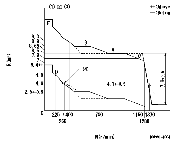
N:Pump speed
R:Rack position (mm)
(1)Lever ratio: RT
(2)Target shim dimension: TH
(3)Tolerance for racks not indicated: +-0.05mm.
(4)Damper spring setting
----------
RT=0.8 TH=2mm
----------
----------
RT=0.8 TH=2mm
----------
Speed control lever angle

F:Full speed
----------
----------
a=7deg+-5deg
----------
----------
a=7deg+-5deg
0000000901

F:Full load
I:Idle
(1)Stopper bolt setting
----------
----------
a=10deg+-5deg b=34deg+-3deg
----------
----------
a=10deg+-5deg b=34deg+-3deg
Stop lever angle

N:Pump normal
S:Stop the pump.
----------
----------
a=60deg+-5deg b=73deg+-5deg
----------
----------
a=60deg+-5deg b=73deg+-5deg
Timing setting

(1)Pump vertical direction
(2)Position of "Z" mark at the No 1 cylinder's beginning of injection (governor side)
(3)B.T.D.C.: aa (set timing)
(4)-
----------
aa=8deg
----------
a=(180deg)
----------
aa=8deg
----------
a=(180deg)
Information:
Start By:a. remove timing gear coverb. remove flywheel housing*c. remove engine oil cooler**d. remove oil filter base***Put the engine in time before the flywheel housing is removed. See the topic, "Finding Top Center Compression Position For No. 1 Piston" in Testing & Adjusting Manual SENR6471.**These operations must be done to install Tool (A) on the engine.
Typical Example1. Fasten the engine on Tool (A). The weight of the engine is 1362 kg (3000 lb).2. Remove the bolts and nuts that hold air cleaner group (1), pipe assembly (3), bracket assembly (4) and lifting plate (5) as a unit to the engine. Fasten a hoist to the unit and remove it from the engine. The weight of the unit is approximately 39 kg (85 lb).3. Remove tube assembly (2) from the engine.
Typical Example4. Install the two bolts to hold the primary fuel filter bracket (6) in place while the engine is turned with Tool (A). 5. Turn the engine to the position shown with Tool (A). Remove rod bearing caps (8) from the ends of the connecting rods. Push the connecting rods away from the crankshaft.6. Remove the bolts and remove main bearing caps (7) from the crankshaft. 7. Remove thrust plates (9) from the center main bearing journal. 8. Fasten a hoist to crankshaft (10) with tooling (B). Remove crankshaft (10) from the engine block. The weight of the crankshaft is 159 kg (350 lb). 9. Use Tool (C) to remove outer gear (2) from the end of the crankshaft.10. Use a hammer and chisel to remove the spacer from the crankshaft. 11. Use Tool (D) to remove the gear alignment dowel from the crankshaft.12. Use Tool (C) to remove inner gear (11) from the end of the crankshaft. If new main bearings are not to be installed, put identification on the old main bearings as to their location in the cylinder block and to which main bearings caps they belong.13. Remove main bearings (13) from the cylinder block and the main bearing caps.Install Crankshaft
1. If the dowel was removed from the flywheel end of the crankshaft, install it in the crankshaft to a maximum dimension of 6.4 mm (.25 in).2. Heat the crankshaft gears to a maximum temperature of 205° C (400° F).3. The centerline of inner gear key must be in alignment with the centerline of the dowel hole within 0.51 mm (.020 in). Install crankshaft inner gear (14) on the crankshaft.4. Install the spacer on the crankshaft.5. Install the dowel in the crankshaft. The dowel must be extended no more than 4.1 0.5 mm (.16 .02 in) from the surface of the crankshaft. The dowel in the crankshaft must be in alignment with the notch in crankshaft gear (15).6. Make sure the "V" mark on the crankshaft gear is toward the outside, and install crankshaft gear (15). 7. Thoroughly clean the cylinder block and main bearing caps.
Make sure the upper and lower halves of the main bearings are installed so the bearing tabs fit