Information injection-pump assembly
BOSCH
9 400 618 699
9400618699
ZEXEL
106971-5020
1069715020
NISSAN-DIESEL
1671397179
1671397179
Rating:
Service parts 106971-5020 INJECTION-PUMP ASSEMBLY:
1.
_
6.
COUPLING PLATE
7.
COUPLING PLATE
8.
_
9.
_
11.
Nozzle and Holder
12.
Open Pre:MPa(Kqf/cm2)
22.6(230)
15.
NOZZLE SET
Include in #1:
106971-5020
as INJECTION-PUMP ASSEMBLY
Cross reference number
BOSCH
9 400 618 699
9400618699
ZEXEL
106971-5020
1069715020
NISSAN-DIESEL
1671397179
1671397179
Zexel num
Bosch num
Firm num
Name
106971-5020
9 400 618 699
1671397179 NISSAN-DIESEL
INJECTION-PUMP ASSEMBLY
RD10T03 K 14CE INJECTION PUMP ASSY PE10P PE
RD10T03 K 14CE INJECTION PUMP ASSY PE10P PE
Calibration Data:
Adjustment conditions
Test oil
1404 Test oil ISO4113 or {SAEJ967d}
1404 Test oil ISO4113 or {SAEJ967d}
Test oil temperature
degC
40
40
45
Nozzle and nozzle holder
105780-8140
Bosch type code
EF8511/9A
Nozzle
105780-0000
Bosch type code
DN12SD12T
Nozzle holder
105780-2080
Bosch type code
EF8511/9
Opening pressure
MPa
17.2
Opening pressure
kgf/cm2
175
Injection pipe
Outer diameter - inner diameter - length (mm) mm 8-3-600
Outer diameter - inner diameter - length (mm) mm 8-3-600
Overflow valve
132424-0620
Overflow valve opening pressure
kPa
157
123
191
Overflow valve opening pressure
kgf/cm2
1.6
1.25
1.95
Tester oil delivery pressure
kPa
157
157
157
Tester oil delivery pressure
kgf/cm2
1.6
1.6
1.6
Direction of rotation (viewed from drive side)
Right R
Right R
Injection timing adjustment
Direction of rotation (viewed from drive side)
Right R
Right R
Injection order
10-9-4-3
-6-5-8-7
-2-1
Pre-stroke
mm
3.65
3.6
3.7
Beginning of injection position
Governor side NO.1
Governor side NO.1
Difference between angles 1
Cal 10-9 deg. 45 44.5 45.5
Cal 10-9 deg. 45 44.5 45.5
Difference between angles 2
Cal 10-4 deg. 72 71.5 72.5
Cal 10-4 deg. 72 71.5 72.5
Difference between angles 3
Cal 10-3 deg. 117 116.5 117.5
Cal 10-3 deg. 117 116.5 117.5
Difference between angles 4
Cal 10-6 deg. 144 143.5 144.5
Cal 10-6 deg. 144 143.5 144.5
Difference between angles 5
Cal 10-5 deg. 189 188.5 189.5
Cal 10-5 deg. 189 188.5 189.5
Difference between angles 6
Cal 10-8 deg. 216 215.5 216.5
Cal 10-8 deg. 216 215.5 216.5
Difference between angles 7
Cal 10-7 deg. 261 260.5 261.5
Cal 10-7 deg. 261 260.5 261.5
Difference between angles 8
Cal 10-2 deg. 288 287.5 288.5
Cal 10-2 deg. 288 287.5 288.5
Difference between angles 9
Cal 10-1 deg. 333 332.5 333.5
Cal 10-1 deg. 333 332.5 333.5
Injection quantity adjustment
Adjusting point
A
Rack position
12.1
Pump speed
r/min
750
750
750
Average injection quantity
mm3/st.
138.5
137.5
139.5
Max. variation between cylinders
%
0
-2.5
2.5
Basic
*
Fixing the lever
*
Boost pressure
kPa
38
38
Boost pressure
mmHg
285
285
Injection quantity adjustment_02
Adjusting point
B
Rack position
10.8
Pump speed
r/min
500
500
500
Average injection quantity
mm3/st.
109.5
107.5
111.5
Max. variation between cylinders
%
0
-4
4
Fixing the lever
*
Boost pressure
kPa
0
0
0
Boost pressure
mmHg
0
0
0
Injection quantity adjustment_03
Adjusting point
C
Rack position
7.6+-0.5
Pump speed
r/min
300
300
300
Average injection quantity
mm3/st.
13
11.9
14.1
Max. variation between cylinders
%
0
-15
15
Fixing the rack
*
Boost pressure
kPa
0
0
0
Boost pressure
mmHg
0
0
0
Injection quantity adjustment_04
Adjusting point
D
Rack position
-
Pump speed
r/min
100
100
100
Average injection quantity
mm3/st.
130
125
135
Fixing the lever
*
Boost pressure
kPa
0
0
0
Boost pressure
mmHg
0
0
0
Rack limit
*
Boost compensator adjustment
Pump speed
r/min
500
500
500
Rack position
10.8
Boost pressure
kPa
16
9.3
22.7
Boost pressure
mmHg
120
70
170
Boost compensator adjustment_02
Pump speed
r/min
500
500
500
Rack position
(12.1)
Boost pressure
kPa
30
28.7
31.3
Boost pressure
mmHg
225
215
235
Timer adjustment
Pump speed
r/min
300+100
Advance angle
deg.
0
0
0
Remarks
Start
Start
Timer adjustment_02
Pump speed
r/min
600
Advance angle
deg.
1.7
1.2
2.2
Timer adjustment_03
Pump speed
r/min
900
Advance angle
deg.
3.4
2.9
3.9
Timer adjustment_04
Pump speed
r/min
1250+50
Advance angle
deg.
5.5
5
6
Remarks
Finish
Finish
Test data Ex:
Governor adjustment
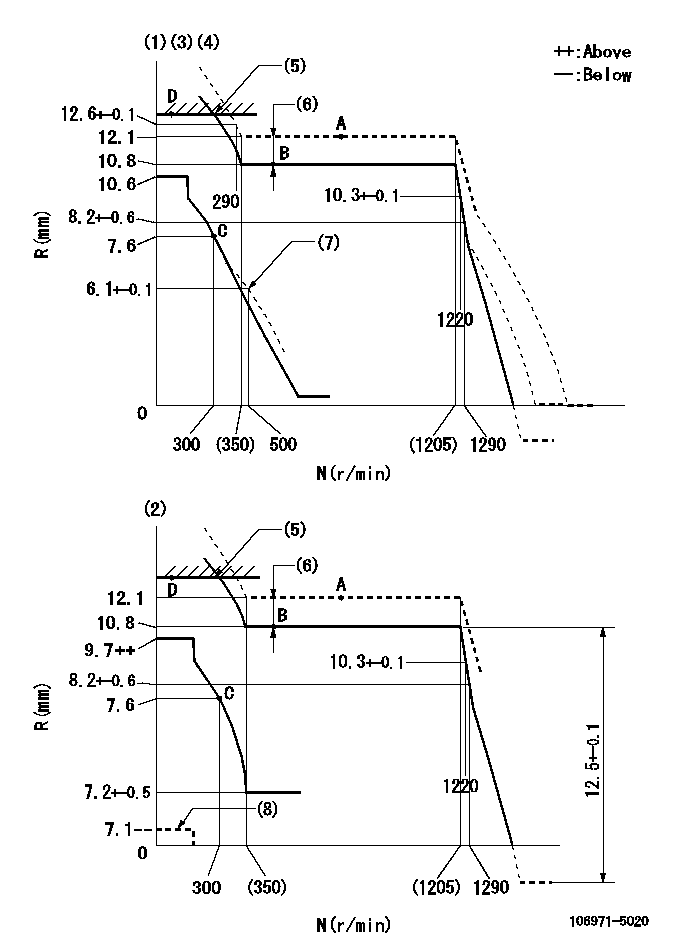
N:Pump speed
R:Rack position (mm)
(1)Variable speed specification (load control lever at full position)
(2)Minimum - maximum speed specification (speed control lever full position)
(3)Target notch: K
(4)Tolerance for racks not indicated: +-0.05mm.
(5)RACK LIMIT
(6)Boost compensator stroke: BCL
(7)Damper spring setting
(8)Set the load lever at the stop position.
----------
K=17 BCL=(1.3)mm
----------
----------
K=17 BCL=(1.3)mm
----------
Speed control lever angle

F:Full speed
I:Idle
S:Stop
----------
----------
a=8deg+-5deg b=32deg+-3deg c=23deg+-5deg
----------
----------
a=8deg+-5deg b=32deg+-3deg c=23deg+-5deg
0000000901
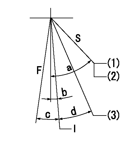
F:Full load
I:Idle
S:Stop
(1)Position where contacts boss
(2)Rack position = aa or less (speed = bb)
(3)Rack position = cc (speed = dd)
----------
aa=7.1mm bb=0r/min cc=7.1-0.2mm dd=0r/min
----------
a=(46deg) b=0deg+-5deg c=6deg+-3deg d=21deg+-5deg
----------
aa=7.1mm bb=0r/min cc=7.1-0.2mm dd=0r/min
----------
a=(46deg) b=0deg+-5deg c=6deg+-3deg d=21deg+-5deg
0000001501 GOV FULL LOAD ADJUSTMENT

Title1:Full load stopper adjustment
Title2:Governor set speed
LABEL1:Distinguishing
LABEL2:Pump speed (r/min)
LABEL3:Ave. injection quantity (mm3/st)
LABEL4:Max. var. bet. cyl.
LABEL5:Remarks
LABEL6:Distinguishing
LABEL7:Governor set speed (r/min)
LABEL8:Maximum no-load speed (r/min)
LABEL9:Remarks
(1)Adjustment conditions are the same as those for measuring injection quantity.
(2)At high idle rack position L
----------
L=8.2mm
----------
a1=A a2=B a3=C a4=D r1=- r2=750r/min r3=700r/min r4=700r/min Q1=- Q2=138.5+-1mm3/st Q3=126.5+-1mm3/st Q4=103+-1mm3/st c1=- c2=+-2.5 c3=+-2.5 c4=+-2.5 a5=24 a6=23 a7=22 a8=21 a9=20 a10=19 a11=18 a12=17 a13=16 a14=15 a15=- r5=1200r/min r6=1150r/min r7=1100r/min r8=1050r/min r9=1000r/min r10=950r/min r11=900r/min r12=850r/min r13=800r/min r14=750r/min r15=- R5=1290+-30r/min R6=1235+-28r/min R7=1180+-27r/min R8=1130+-26r/min R9=1075+-25r/min R10=1020+-23r/min R11=965+-22r/min R12=915+-22r/min R13=860+-20r/min R14=805+-18r/min R15=-
----------
L=8.2mm
----------
a1=A a2=B a3=C a4=D r1=- r2=750r/min r3=700r/min r4=700r/min Q1=- Q2=138.5+-1mm3/st Q3=126.5+-1mm3/st Q4=103+-1mm3/st c1=- c2=+-2.5 c3=+-2.5 c4=+-2.5 a5=24 a6=23 a7=22 a8=21 a9=20 a10=19 a11=18 a12=17 a13=16 a14=15 a15=- r5=1200r/min r6=1150r/min r7=1100r/min r8=1050r/min r9=1000r/min r10=950r/min r11=900r/min r12=850r/min r13=800r/min r14=750r/min r15=- R5=1290+-30r/min R6=1235+-28r/min R7=1180+-27r/min R8=1130+-26r/min R9=1075+-25r/min R10=1020+-23r/min R11=965+-22r/min R12=915+-22r/min R13=860+-20r/min R14=805+-18r/min R15=-
Information:
Termination Date
October 31, 1993Problem
Certain 2S7264 and 3S1467 Fuel Injection Pump Assemblies need to be removed from parts stock.
Action Required
Remove all 2S7264 and 3S1467 Fuel Injection Pump Assemblies from parts stock with date codes of December 1992 through March 1993. The date code appears at the bottom of the part number label on the pump box. The first two numbers indicate the month and the next two numbers indicate the year as shown in the example below:
Service Claim Allowances
Submit one claim for all 2S7264 and 3S1467 Fuel Injection Pump Assemblies removed from parts stock.
US and Canadian Dealers Only - When submitting a parts stock claim use 99Z00007 in the Product Identification Number Field.
Parts Disposition
U.S. And Canadian Dealers
Return all 2S7264 and 3S1467 Fuel Injection Pump Assemblies that are removed from parts stock and a copy of the claim to:
Caterpillar Inc.
Memory Lane
B Receiving
York, PA 17402
Attention: Quality Dept./PI7318
All Other Dealers
Handle the parts in accordance with your Warranty Bulletin on warranty parts handling.
Have questions with 106971-5020?
Group cross 106971-5020 ZEXEL
Nissan-Diesel
106971-5020
9 400 618 699
1671397179
INJECTION-PUMP ASSEMBLY
RD10T03
RD10T03