Information injection-pump assembly
ZEXEL
106971-3213
1069713213
HINO
220009303A
220009303a
Rating:
Service parts 106971-3213 INJECTION-PUMP ASSEMBLY:
1.
_
7.
COUPLING PLATE
8.
_
9.
_
11.
Nozzle and Holder
23600-2750A
12.
Open Pre:MPa(Kqf/cm2)
14.7{150}/21.6{220}
14.
NOZZLE
Include in #1:
106971-3213
as INJECTION-PUMP ASSEMBLY
Cross reference number
ZEXEL
106971-3213
1069713213
HINO
220009303A
220009303a
Zexel num
Bosch num
Firm num
Name
Calibration Data:
Adjustment conditions
Test oil
1404 Test oil ISO4113 or {SAEJ967d}
1404 Test oil ISO4113 or {SAEJ967d}
Test oil temperature
degC
40
40
45
Nozzle and nozzle holder
105780-8250
Bosch type code
1 688 901 101
Nozzle
105780-0120
Bosch type code
1 688 901 990
Nozzle holder
105780-2190
Opening pressure
MPa
20.7
Opening pressure
kgf/cm2
211
Injection pipe
Outer diameter - inner diameter - length (mm) mm 8-3-600
Outer diameter - inner diameter - length (mm) mm 8-3-600
Overflow valve
134424-4120
Overflow valve opening pressure
kPa
255
221
289
Overflow valve opening pressure
kgf/cm2
2.6
2.25
2.95
Tester oil delivery pressure
kPa
255
255
255
Tester oil delivery pressure
kgf/cm2
2.6
2.6
2.6
RED3 control unit part number
407910-2
470
RED3 rack sensor specifications
mm
15
Direction of rotation (viewed from drive side)
Right R
Right R
Injection timing adjustment
Direction of rotation (viewed from drive side)
Right R
Right R
Injection order
1-10-9-4
-3-6-5-8
-7-2
Pre-stroke
mm
4.2
4.14
4.2
Beginning of injection position
Governor side NO.1
Governor side NO.1
Difference between angles 1
Cal 1-10 deg. 27 26.75 27.25
Cal 1-10 deg. 27 26.75 27.25
Difference between angles 2
Cal 1-9 deg. 72 71.75 72.25
Cal 1-9 deg. 72 71.75 72.25
Difference between angles 3
Cal 1-4 deg. 99 98.75 99.25
Cal 1-4 deg. 99 98.75 99.25
Difference between angles 4
Cal 1-3 deg. 144 143.75 144.25
Cal 1-3 deg. 144 143.75 144.25
Difference between angles 5
Cal 1-6 deg. 171 170.75 171.25
Cal 1-6 deg. 171 170.75 171.25
Difference between angles 6
Cal 1-5 deg. 216 215.75 216.25
Cal 1-5 deg. 216 215.75 216.25
Difference between angles 7
Cal 1-8 deg. 243 242.75 243.25
Cal 1-8 deg. 243 242.75 243.25
Difference between angles 8
Cal 1-7 deg. 288 287.75 288.25
Cal 1-7 deg. 288 287.75 288.25
Difference between angles 9
Cyl.1-2 deg. 315 314.75 315.25
Cyl.1-2 deg. 315 314.75 315.25
Injection quantity adjustment
Rack position
(12.8)
Vist
V
1.45
1.45
1.45
Pump speed
r/min
700
700
700
Average injection quantity
mm3/st.
135.5
133.5
137.5
Max. variation between cylinders
%
0
-4
4
Basic
*
Injection quantity adjustment_02
Rack position
(8.4)
Vist
V
2.31
2.25
2.37
Pump speed
r/min
410
410
410
Average injection quantity
mm3/st.
18
15
21
Max. variation between cylinders
%
0
-10
10
Governor adjustment
Pump speed
r/min
720--
Advance angle
deg.
0
0
0
Load
2/5
Remarks
Start
Start
Governor adjustment_02
Pump speed
r/min
670
Advance angle
deg.
0.3
Load
2/5
Governor adjustment_03
Pump speed
r/min
(790--)
Advance angle
deg.
2
1.7
2.3
Load
5/5
Governor adjustment_04
Pump speed
r/min
870
Advance angle
deg.
2
1.7
2.3
Load
4/5
Governor adjustment_05
Pump speed
r/min
(960--)
Advance angle
deg.
2
1.7
2.3
Load
5/5
Governor adjustment_06
Pump speed
r/min
1080-50
Advance angle
deg.
6.75
6.45
7.05
Load
5/5
Remarks
Finish
Finish
Test data Ex:
Speed control lever angle
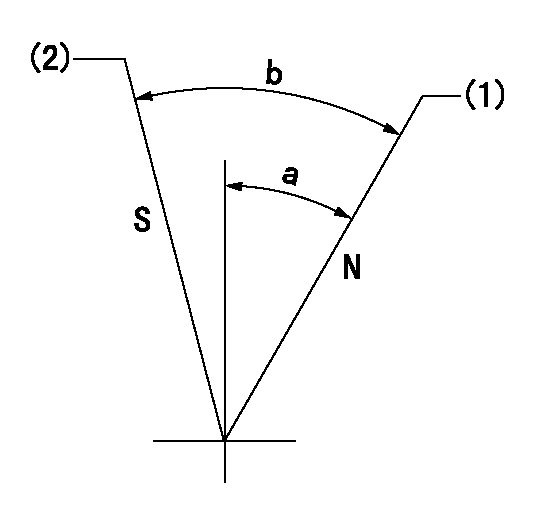
N:Pump normal
S:Stop the pump.
(1)Rack position = aa
(2)Rack position bb
----------
aa=16mm bb=1mm
----------
a=19deg+-5deg b=29deg+-5deg
----------
aa=16mm bb=1mm
----------
a=19deg+-5deg b=29deg+-5deg
0000000901

(1)Pump vertical direction
(2)Coupling's key groove position at No 1 cylinder's beginning of injection
(3)-
(4)-
----------
----------
a=(80deg)
----------
----------
a=(80deg)
Stop lever angle

(Rs) rack sensor specifications
(C/U) control unit part number
(V) Rack sensor output voltage
(R) Rack position (mm)
1. Confirming governor output characteristics (rack 15 mm, span 6 mm)
(1)When the output voltages of the rack sensor are V1 and V2, check that the rack positions R1 and R2 in the table above are satisfied.
----------
----------
----------
----------
Information:
Problem
The fuel lines on certain D9N Tractors, 589 Pipelayers, 631E Tractors, 637E Tractors, 657E Scrapers, 768C Tractors, 769C Trucks, 834B Tractors, and 988B Loaders may fail. New fuel line groups can be installed that have a longer service life.
Affected Product
Model & Identification Number
Group 1
D9N (1JD1288, 1JD1295, 1JD1296, 1JD1298-3280)
589 (31Z423-469)
631E (1AB965-1456; 1NB769-771)
637E TR (1FB361-537; 1JB612-724)
657E SC (90Z186-209; 91Z317-448)
768C (02X360-370)
769C (01X4394, 01X4403, 01X4418, 01X4420-5960)
Group 2
988B (50W08961, 50W8962, 50W8964-11257)
Group 3
834B (92Z368, 92Z370, 92Z373-512)
Parts Needed
Group 1
4 - 4B4274 Washer2 - 7C6525 Fuel Line Clamp2 - 7C6589 Fuel Line Clamp1 - 6I0030 Lines Group6 - 5M2894 Washer4 - 9N3388 Screw6 - 0S0509 BoltGroup 2
4 - 4B4274 Washer2 - 7C6525 Fuel Line Clamp2 - 7C6589 Fuel Line Clamp1 - 6I0030 Lines Group11 - 5M2894 Washer4 - 9N3388 Screw1 - 4P8261 Bracket1 - 4P8385 Bracket2 - 5P0537 Washer5 - 0S1571 Bolt6 - 0S0509 Bolt2 - 0S1615 Bolt3 - 8T1296 Washer1 - 1010462 RodGroup 3
4 - 4B4274 Washer2 - 7C6525 Fuel Line Clamp2 - 7C6589 Fuel Line Clamp1 - 1029884 Lines Group4 - 9N3388 Screw5 - 5M2894 Washer4 - 0S0509 Bolt1 - 0S1594 BoltAction Required
Parts Stock
Remove all 7C6931, 7C6932, 7C6933, 7C6934, 7C6935, 7C6936, 7C6937, and 7C6938 Fuel Lines from parts stock.
Affected Product
Remove the existing fuel lines and install the new fuel injection line group as a group. Do not disassemble the fuel line groups and install them one line at a time. See the attached (pending) procedure.
Do not over tighten the screws of the metal-to- metal fuel line clamps. Use a 6V6069 Torque Screwdriver or similar tool to tighten the screw to a torque of 2.25 N m (20 lb.in.).
Service Claim Allowances
Parts Stock
Submit one claim for all 7C6931, 7C6932, 7C6933, 7C6934, 7C6935, 7C6936, 7C6937, and 7C6938 Fuel Lines removed from parts stock.
Affected Product
This is a 3-hour job.
Parts Disposition
Handle the parts in accordance with your Warranty Bulletin on warranty parts handling.
Attach. (1-Rework Procedure)Rework Procedure
Refer to the parts list and illustrations. Replace the existing fuel lines and their related parts with the new parts listed for each group.
To insure that the clamp locations are correct, install fuel line group as assembled. In a case where it is necessary to remove the clamps, mark their locations to insure correct positions when assembling.
1. Clean and paint the new 6I0030 or 102-9884 Fuel Line Group before proceeding to the job site.A) Install 5F2807 Plastic Caps and 2F2990 Plastic Plugs on the ends of the lines.B) Clean and paint the fuel line group.C) After drying, do not remove the plastic plugs and caps until the fuel line group is ready to be installed on the engine. Transport the fuel line group in it's original shipping box.2. Remove all mounting bolts from the fuel line brackets at the aftercooler housing. New mounting bolts and washers will be used. Keep the washers. The washers may be needed later as spacers.3. Remove the existing three line clamps from the 9Y4577 Bracket which is attached to the backside of the fuel injection pump (See Illustration 1). New 7C6525 Clamps, 7C6589 Clamps, 9N3388 Screws, and 4B4274 Washers