Information injection-pump assembly
ZEXEL
106971-3202
1069713202
HINO
220008882A
220008882a

Rating:
Service parts 106971-3202 INJECTION-PUMP ASSEMBLY:
1.
_
7.
COUPLING PLATE
8.
_
9.
_
11.
Nozzle and Holder
23600-2750A
12.
Open Pre:MPa(Kqf/cm2)
14.7{150}/21.6{220}
14.
NOZZLE
Include in #1:
106971-3202
as INJECTION-PUMP ASSEMBLY
Cross reference number
ZEXEL
106971-3202
1069713202
HINO
220008882A
220008882a
Zexel num
Bosch num
Firm num
Name
Calibration Data:
Adjustment conditions
Test oil
1404 Test oil ISO4113 or {SAEJ967d}
1404 Test oil ISO4113 or {SAEJ967d}
Test oil temperature
degC
40
40
45
Nozzle and nozzle holder
105780-8250
Bosch type code
1 688 901 101
Nozzle
105780-0120
Bosch type code
1 688 901 990
Nozzle holder
105780-2190
Opening pressure
MPa
20.7
Opening pressure
kgf/cm2
211
Injection pipe
Outer diameter - inner diameter - length (mm) mm 8-3-600
Outer diameter - inner diameter - length (mm) mm 8-3-600
Overflow valve
134424-4120
Overflow valve opening pressure
kPa
255
221
289
Overflow valve opening pressure
kgf/cm2
2.6
2.25
2.95
Tester oil delivery pressure
kPa
255
255
255
Tester oil delivery pressure
kgf/cm2
2.6
2.6
2.6
Direction of rotation (viewed from drive side)
Right R
Right R
Injection timing adjustment
Direction of rotation (viewed from drive side)
Right R
Right R
Injection order
1-10-9-4
-3-6-5-8
-7-2
Pre-stroke
mm
4.2
4.14
4.2
Beginning of injection position
Governor side NO.1
Governor side NO.1
Difference between angles 1
Cal 1-10 deg. 27 26.75 27.25
Cal 1-10 deg. 27 26.75 27.25
Difference between angles 2
Cal 1-9 deg. 72 71.75 72.25
Cal 1-9 deg. 72 71.75 72.25
Difference between angles 3
Cal 1-4 deg. 99 98.75 99.25
Cal 1-4 deg. 99 98.75 99.25
Difference between angles 4
Cal 1-3 deg. 144 143.75 144.25
Cal 1-3 deg. 144 143.75 144.25
Difference between angles 5
Cal 1-6 deg. 171 170.75 171.25
Cal 1-6 deg. 171 170.75 171.25
Difference between angles 6
Cal 1-5 deg. 216 215.75 216.25
Cal 1-5 deg. 216 215.75 216.25
Difference between angles 7
Cal 1-8 deg. 243 242.75 243.25
Cal 1-8 deg. 243 242.75 243.25
Difference between angles 8
Cal 1-7 deg. 288 287.75 288.25
Cal 1-7 deg. 288 287.75 288.25
Difference between angles 9
Cyl.1-2 deg. 315 314.75 315.25
Cyl.1-2 deg. 315 314.75 315.25
Injection quantity adjustment
Adjusting point
-
Rack position
12.6
Pump speed
r/min
700
700
700
Average injection quantity
mm3/st.
132.5
129.5
135.5
Max. variation between cylinders
%
0
-4
4
Basic
*
Fixing the rack
*
Standard for adjustment of the maximum variation between cylinders
*
Injection quantity adjustment_02
Adjusting point
Z
Rack position
8+-0.5
Pump speed
r/min
455
455
455
Average injection quantity
mm3/st.
15
12
18
Max. variation between cylinders
%
0
-10
10
Fixing the rack
*
Standard for adjustment of the maximum variation between cylinders
*
Injection quantity adjustment_03
Adjusting point
A
Rack position
R1(12.6)
Pump speed
r/min
700
700
700
Average injection quantity
mm3/st.
132.5
130.5
134.5
Basic
*
Fixing the lever
*
Injection quantity adjustment_04
Adjusting point
B
Rack position
R1+0.25
Pump speed
r/min
1100
1100
1100
Average injection quantity
mm3/st.
118
112
124
Fixing the lever
*
Timer adjustment
Pump speed
r/min
720--
Advance angle
deg.
0
0
0
Load
2/5
Remarks
Start
Start
Timer adjustment_02
Pump speed
r/min
670
Advance angle
deg.
0.3
Load
2/5
Timer adjustment_03
Pump speed
r/min
(790--)
Advance angle
deg.
2
1.7
2.3
Load
5/5
Timer adjustment_04
Pump speed
r/min
880
Load
2/5
Remarks
Measure the actual advance angle.
Measure the actual advance angle.
Timer adjustment_05
Pump speed
r/min
890
Advance angle
deg.
2
1.7
2.3
Load
4/5
Timer adjustment_06
Pump speed
r/min
(960--)
Advance angle
deg.
2
1.7
2.3
Load
5/5
Timer adjustment_07
Pump speed
r/min
1080-50
Advance angle
deg.
6.75
6.45
7.05
Load
5/5
Remarks
Finish
Finish
Test data Ex:
Governor adjustment
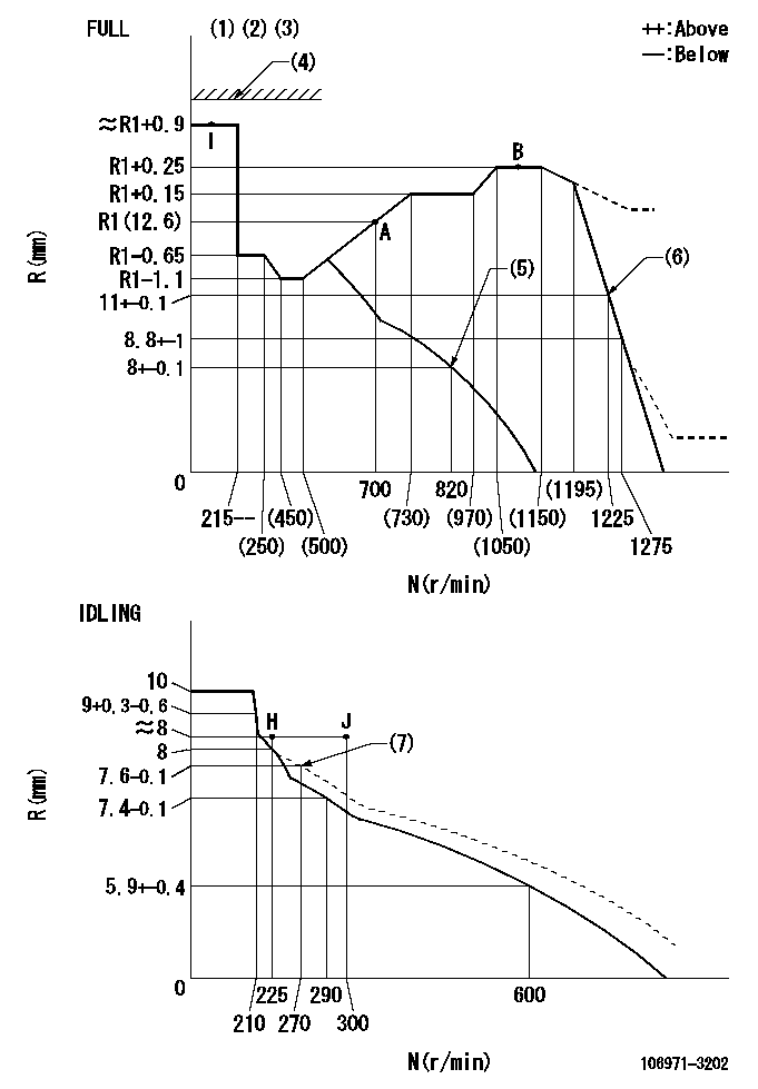
N:Pump speed
R:Rack position (mm)
(1)Torque cam stamping: T1
(2)Tolerance for racks not indicated: +-0.05mm.
(3)Set stop lever before governor adjustment. [When setting stop lever after governor adjustment, confirm that point I (Ra) can be obtained at full setting.]
(4)Stop lever's normal position setting: equivalent to RA
(5)Air cylinder OFF
(6)Air cylinder ON
(7)Damper spring setting
----------
T1=AD25 Ra=(R1+0.7)mm RA=18mm
----------
----------
T1=AD25 Ra=(R1+0.7)mm RA=18mm
----------
Speed control lever angle
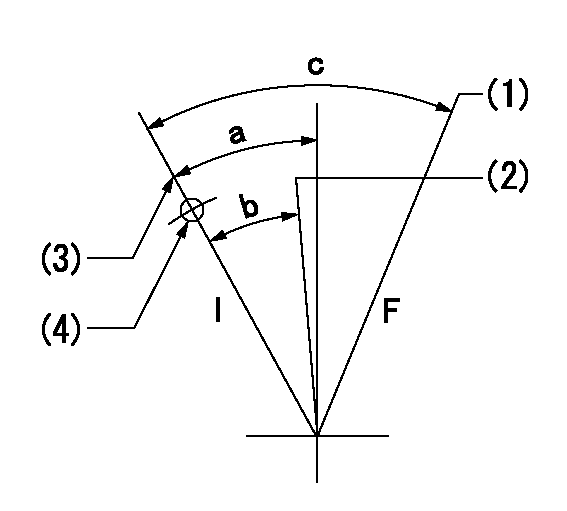
F:Full speed
I:Idle
(1)When air cylinder ON.
(2)When air cylinder OFF.
(3)Stopper bolt set position 'H'
(4)Use the hole at R = aa
----------
aa=47mm
----------
a=20deg+-5deg b=(12deg) c=(30.5deg)+-3deg
----------
aa=47mm
----------
a=20deg+-5deg b=(12deg) c=(30.5deg)+-3deg
Stop lever angle
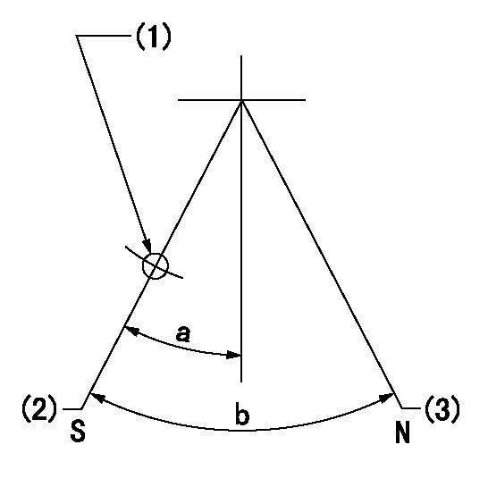
N:Pump normal
S:Stop the pump.
(1)Use the pin at R = aa
(2)Set the stopper bolt so that speed = bb and rack position = cc. (Confirm non-injection.)
(3)Set the stopper bolt so that rack position = dd.
----------
aa=40mm bb=0r/min cc=4+-0.3mm dd=18mm
----------
a=8.5deg+-5deg b=30deg+-5deg
----------
aa=40mm bb=0r/min cc=4+-0.3mm dd=18mm
----------
a=8.5deg+-5deg b=30deg+-5deg
0000001501 AIR CYLINDER
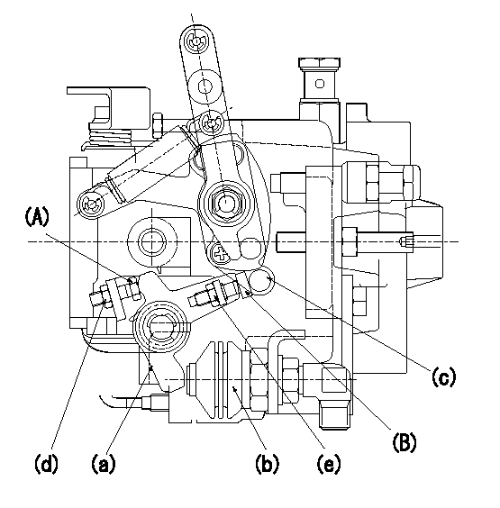
(A) stopper bolt
(B) stopper bolt
(a) lever
(b) air cylinder
(c) speed lever
(d) Nut
(e) nut
1. Stopper bolt A adjusting method
(1)When the air cylinder pressure is P1, confirm that there is a clearance between the stopper bolt (A) and the lever (a).
(2)Then, screw in the stopper bolt A until it contacts the lever a.
(3)Further screw in L1 and set temporarily.
(4)Apply P2 to the air cylinder.
(5)Confirm that the speed lever (c) operates between idling and full speed positions.
(6)Fix the stopper bolt A using nut d.
2. Stopper bolt <B> adjustment method.
(1)At air cylinder pressure P1, pump speed N1 and rack position is Ra, adjust stopper bolt (B) so that the speed lever (c) is in the stop position.
(2)Move the lever a several times and then fix the stopper bolt B using the nut e.
(3)Nut d tightening torque: T1
(4)Nut e tightening torque: T2
----------
P1=0kPa(0kgf/cm2) L1=0.5mm P2=686+98kPa(7+1kgf/cm2) N1=820r/min Ra=8+-0.1mm T1=4.9~7N-m(0.5~0.7kgf-m) T2=4.9~7N-m(0.5~0.7kgf-m)
----------
----------
P1=0kPa(0kgf/cm2) L1=0.5mm P2=686+98kPa(7+1kgf/cm2) N1=820r/min Ra=8+-0.1mm T1=4.9~7N-m(0.5~0.7kgf-m) T2=4.9~7N-m(0.5~0.7kgf-m)
----------
Timing setting

(1)Pump vertical direction
(2)Coupling's key groove position at No 1 cylinder's beginning of injection
(3)-
(4)-
----------
----------
a=(80deg)
----------
----------
a=(80deg)
Information:
Cut apart used filters to see contaminants. Use a 6V790S FilterCutter
to cut the filter housing.
Maintenance for Engines Using Heavy Fuel
Engines operating on heavy fuel must be carefully monitored and maintained.Service intervals must be strictly observed. Operators must be trained toperform a thorough service inspection.
"As Needed" Periodic Activities
Test fuel as it is delivered. Identify contaminant levels immediately and notify appropriate operations personnel.
Before storage, test for compatibility between fuel in the tanks and the fuel being purchased. Keep the fuel in separate tanks if possible.
Use regular S.O.S oil analysis to determine if there are wear particles in the oil, and maintain the proper TBN level.
Request infrared analysis on used oils to determine the effects of burning heavy fuel on the crankcase oil.
Daily Activities
Maintain and monitor fuel treatment equipment.
Record engine temperatures to assure adequate jacket water temperature, aftercooler temperature, and air intake temperature.
If equipped with a turbocharger water wash attachment, wash the turbocharger exhaust turbine. It is necessary to remove deposits from the turbine side of the turbocharger. (A washer attachment which does this is available on 3600 Family Engines.)
Check exhaust thermocouples and record exhaust temperatures. Be alert for worn exhaust valves.
Measure valve stem projection when new; use a stationary point such asthe valve cover gasket surface for a reference point. Record the measurementsfor each valve for later follow-up measurements. If valve stem projection movesmore than 1.25 mm (.050 in.) consider disassembly to find the reason. Anotherway to observe valve face wear is to measure and record changes on valve lashover a period of time.
Monitor fuel and oil filter differentials every shift. Check for filter plugging.
Drain settling and fuel tank bottoms daily. Take note if there is excessive water or sediment.
Every 1000 Hours
Check one cylinder head for exhaust valve seating and carbon build-up. Check the fuel injectors for adequate nozzle spray pattern. Make sure the valve rotators are operating.
Clean the turbocharger (exhaust turbine) (3500 and 3600 Family Engines without washers).
Operating the Engine at Low Load
If you're expecting to operate your engine at part load for extendedperiods, switch to No.2 diesel fuel or marine diesel oil. (Make sure the fuelinjectors are not run without fuel during the switch.)
The following chart shows the relationship between engine load and length oftime. It will guide you on what type of fuel to burn in light load applications.
Chart with time and numbers.
Other Heavy Fuel Tips
Here are some things to keep in mind when using heavy fuels.
Cut apart used filters to see contaminants. As contamination levels increase, the quality of diesel fuel is generally decreasing.
As fuel quality decreases, it becomes even more important to have good fuel treatment systems. The treatment system can sometimes compensate for poor fuel quality. ..but there is less margin for error with a system that is not working correctly.
Often, diesel engines cannot operate on fuel that is straight from the fuel tank (bunkered).
Viscosity does not relate to quality. Do not use fuel thickness