Information injection-pump assembly
ZEXEL
106971-3192
1069713192
HINO
220008872A
220008872a
Rating:
Service parts 106971-3192 INJECTION-PUMP ASSEMBLY:
1.
_
7.
COUPLING PLATE
8.
_
9.
_
11.
Nozzle and Holder
23600-2750A
12.
Open Pre:MPa(Kqf/cm2)
14.7{150}/21.6{220}
14.
NOZZLE
Include in #1:
106971-3192
as INJECTION-PUMP ASSEMBLY
Cross reference number
ZEXEL
106971-3192
1069713192
HINO
220008872A
220008872a
Zexel num
Bosch num
Firm num
Name
Calibration Data:
Adjustment conditions
Test oil
1404 Test oil ISO4113 or {SAEJ967d}
1404 Test oil ISO4113 or {SAEJ967d}
Test oil temperature
degC
40
40
45
Nozzle and nozzle holder
105780-8250
Bosch type code
1 688 901 101
Nozzle
105780-0120
Bosch type code
1 688 901 990
Nozzle holder
105780-2190
Opening pressure
MPa
20.7
Opening pressure
kgf/cm2
211
Injection pipe
Outer diameter - inner diameter - length (mm) mm 8-3-600
Outer diameter - inner diameter - length (mm) mm 8-3-600
Overflow valve
134424-4120
Overflow valve opening pressure
kPa
255
221
289
Overflow valve opening pressure
kgf/cm2
2.6
2.25
2.95
Tester oil delivery pressure
kPa
255
255
255
Tester oil delivery pressure
kgf/cm2
2.6
2.6
2.6
Direction of rotation (viewed from drive side)
Right R
Right R
Injection timing adjustment
Direction of rotation (viewed from drive side)
Right R
Right R
Injection order
1-10-9-4
-3-6-5-8
-7-2
Pre-stroke
mm
4.2
4.14
4.2
Beginning of injection position
Governor side NO.1
Governor side NO.1
Difference between angles 1
Cal 1-10 deg. 27 26.75 27.25
Cal 1-10 deg. 27 26.75 27.25
Difference between angles 2
Cal 1-9 deg. 72 71.75 72.25
Cal 1-9 deg. 72 71.75 72.25
Difference between angles 3
Cal 1-4 deg. 99 98.75 99.25
Cal 1-4 deg. 99 98.75 99.25
Difference between angles 4
Cal 1-3 deg. 144 143.75 144.25
Cal 1-3 deg. 144 143.75 144.25
Difference between angles 5
Cal 1-6 deg. 171 170.75 171.25
Cal 1-6 deg. 171 170.75 171.25
Difference between angles 6
Cal 1-5 deg. 216 215.75 216.25
Cal 1-5 deg. 216 215.75 216.25
Difference between angles 7
Cal 1-8 deg. 243 242.75 243.25
Cal 1-8 deg. 243 242.75 243.25
Difference between angles 8
Cal 1-7 deg. 288 287.75 288.25
Cal 1-7 deg. 288 287.75 288.25
Difference between angles 9
Cyl.1-2 deg. 315 314.75 315.25
Cyl.1-2 deg. 315 314.75 315.25
Injection quantity adjustment
Adjusting point
-
Rack position
12.6
Pump speed
r/min
700
700
700
Average injection quantity
mm3/st.
132.5
129.5
135.5
Max. variation between cylinders
%
0
-4
4
Basic
*
Fixing the rack
*
Standard for adjustment of the maximum variation between cylinders
*
Injection quantity adjustment_02
Adjusting point
Z
Rack position
8+-0.5
Pump speed
r/min
455
455
455
Average injection quantity
mm3/st.
15
12
18
Max. variation between cylinders
%
0
-10
10
Fixing the rack
*
Standard for adjustment of the maximum variation between cylinders
*
Injection quantity adjustment_03
Adjusting point
A
Rack position
R1(12.6)
Pump speed
r/min
700
700
700
Average injection quantity
mm3/st.
132.5
130.5
134.5
Basic
*
Fixing the lever
*
Injection quantity adjustment_04
Adjusting point
B
Rack position
R1+0.25
Pump speed
r/min
1100
1100
1100
Average injection quantity
mm3/st.
118
112
124
Fixing the lever
*
Timer adjustment
Pump speed
r/min
720--
Advance angle
deg.
0
0
0
Load
2/5
Remarks
Start
Start
Timer adjustment_02
Pump speed
r/min
670
Advance angle
deg.
0.3
Load
2/5
Timer adjustment_03
Pump speed
r/min
(790--)
Advance angle
deg.
2
1.7
2.3
Load
5/5
Timer adjustment_04
Pump speed
r/min
880
Load
2/5
Remarks
Measure the actual advance angle.
Measure the actual advance angle.
Timer adjustment_05
Pump speed
r/min
890
Advance angle
deg.
2
1.7
2.3
Load
4/5
Timer adjustment_06
Pump speed
r/min
(960--)
Advance angle
deg.
2
1.7
2.3
Load
5/5
Timer adjustment_07
Pump speed
r/min
1080-50
Advance angle
deg.
6.75
6.45
7.05
Load
5/5
Remarks
Finish
Finish
Test data Ex:
Governor adjustment
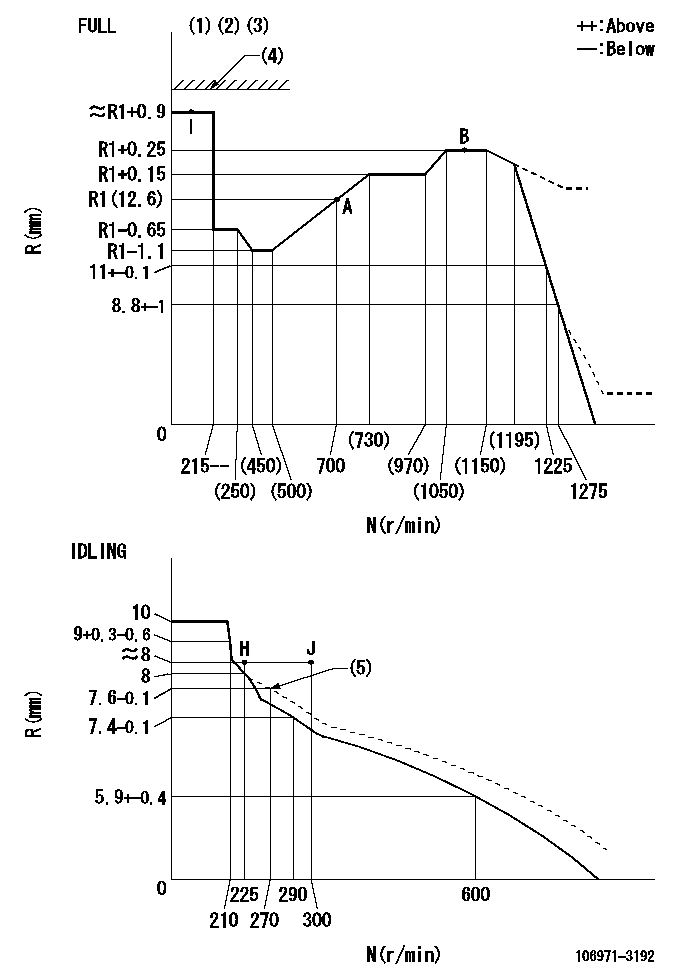
N:Pump speed
R:Rack position (mm)
(1)Torque cam stamping: T1
(2)Tolerance for racks not indicated: +-0.05mm.
(3)Set stop lever before governor adjustment. [When setting stop lever after governor adjustment, confirm that point I (Ra) can be obtained at full setting.]
(4)Stop lever's normal position setting: equivalent to RA
(5)Damper spring setting
----------
T1=AD25 Ra=(R1+0.7)mm RA=18mm
----------
----------
T1=AD25 Ra=(R1+0.7)mm RA=18mm
----------
Speed control lever angle
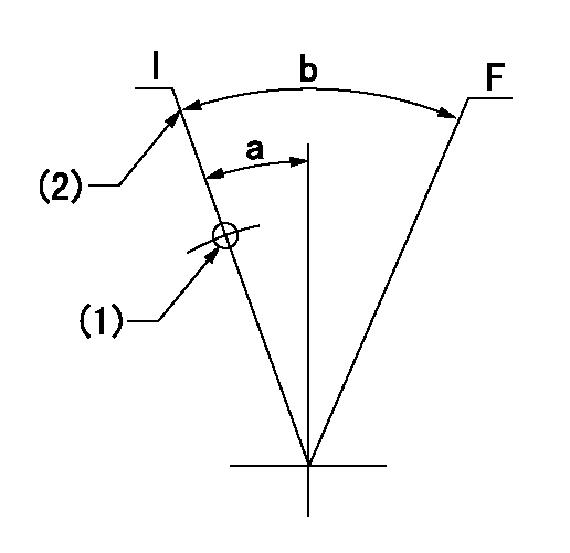
F:Full speed
I:Idle
(1)Use the hole at R = aa
(2)Stopper bolt set position 'H'
----------
aa=47mm
----------
a=20deg+-5deg b=(30.5deg)+-3deg
----------
aa=47mm
----------
a=20deg+-5deg b=(30.5deg)+-3deg
Stop lever angle
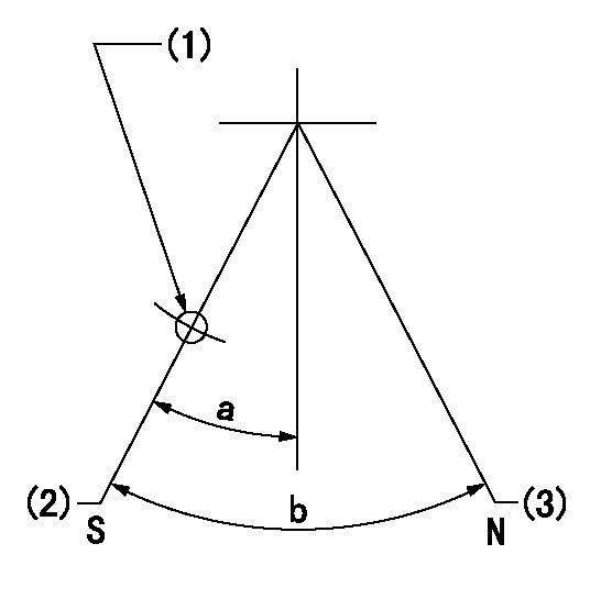
N:Pump normal
S:Stop the pump.
(1)Use the pin at R = aa
(2)Set the stopper bolt so that speed = bb and rack position = cc. (Confirm non-injection.)
(3)Set the stopper bolt so that rack position = dd.
----------
aa=40mm bb=0r/min cc=4+-0.3mm dd=18mm
----------
a=8.5deg+-5deg b=30deg+-5deg
----------
aa=40mm bb=0r/min cc=4+-0.3mm dd=18mm
----------
a=8.5deg+-5deg b=30deg+-5deg
Timing setting

(1)Pump vertical direction
(2)Coupling's key groove position at No 1 cylinder's beginning of injection
(3)-
(4)-
----------
----------
a=(80deg)
----------
----------
a=(80deg)
Information:
(1) Crossbar (from 8B7548 Puller).(2) Spacer plate.(3) S1589 Bolt with two 1S379 Washers.(4) 1D4595 Bolt.(5) 3H465 Plate.(6) 1P2403 Dial Indicator.(7) 1P2394 Adapter Plate.(8) 1P2402 Gauge Body.Make reference to Cylinder Liner Projection in Testing and Adjusting for the complete procedure.1. Install gasket and spacer plate (2) with bolts (3) and two 1S379 Washers. Tighten bolts (3) evenly in four steps: 1st step ... 14 N m (10 lb ft)2nd step ... 35 N m (25 lb ft) 3rd step ... 70 N m (50 lb ft)4th step ... 95 N m (70 lb ft)2. Install tools as shown. Tighten bolts (4) evenly in four steps: 1st step ... 7 N m (5 lb ft)2nd step ... 20 N m (15 lb ft)3rd step ... 35 N m (25 lb ft)4th step ... 70 N m (50 lb ft)3. Measure cylinder liner projection with dial indicator (6) in 1P2402 Gauge Body (8) as shown. Measure at four places around each cylinder liner near the clamped area. Cylinder liner projection measurements for any cylinder liner must be ... 0.033 to 0.175 mm (.0013 to .0069 in)Maximum permissible difference between all four measurements ... 0.05 mm (.002 in)Maximum permissible difference between average projection of any two cylinder liners next to each other ... 0.05 mm (.002 in)Maximum permissible difference between average projection of all cylinder liners under one cylinder head ... 0.10 mm (.004 in) If liner projection is not correct, turn the liner to a new position within the bore. If projection can not be corrected this way, move the liner to a different bore. If the projection can not be corrected this way, make reference to special Instruction, Form No. FMO55228 for complete instructions on the use of 8S3140 Counterboring Tool Arrangement. 4. Minimum permissible depth to machine counterbore to adjust cylinder liner projection ... 0.75 mm (.030 in) Maximum permissible depth to machine counterbore to adjust cylinder liner projection ... 1.14 mm (.045 in)Install a 0.76 mm (.030 in) shim plus any added shims necessary to get the correct cylinder liner projection. Be sure that the 0.75 mm (.030 in) shim is directly under the cylinder liner flange.