Information injection-pump assembly
ZEXEL
106971-3191
1069713191
HINO
220008871A
220008871a
Rating:
Service parts 106971-3191 INJECTION-PUMP ASSEMBLY:
1.
_
4.
SUPPLY PUMP
7.
COUPLING PLATE
8.
_
9.
_
11.
Nozzle and Holder
23600-2750
12.
Open Pre:MPa(Kqf/cm2)
14.7{150}/21.6{220}
14.
NOZZLE
Include in #1:
106971-3191
as INJECTION-PUMP ASSEMBLY
Cross reference number
ZEXEL
106971-3191
1069713191
HINO
220008871A
220008871a
Zexel num
Bosch num
Firm num
Name
Calibration Data:
Adjustment conditions
Test oil
1404 Test oil ISO4113 or {SAEJ967d}
1404 Test oil ISO4113 or {SAEJ967d}
Test oil temperature
degC
40
40
45
Nozzle and nozzle holder
105780-8250
Bosch type code
1 688 901 101
Nozzle
105780-0120
Bosch type code
1 688 901 990
Nozzle holder
105780-2190
Opening pressure
MPa
20.7
Opening pressure
kgf/cm2
211
Injection pipe
Outer diameter - inner diameter - length (mm) mm 8-3-600
Outer diameter - inner diameter - length (mm) mm 8-3-600
Overflow valve
134424-4120
Overflow valve opening pressure
kPa
255
221
289
Overflow valve opening pressure
kgf/cm2
2.6
2.25
2.95
Tester oil delivery pressure
kPa
255
255
255
Tester oil delivery pressure
kgf/cm2
2.6
2.6
2.6
Direction of rotation (viewed from drive side)
Right R
Right R
Injection timing adjustment
Direction of rotation (viewed from drive side)
Right R
Right R
Injection order
1-10-9-4
-3-6-5-8
-7-2
Pre-stroke
mm
4.2
4.14
4.2
Beginning of injection position
Governor side NO.1
Governor side NO.1
Difference between angles 1
Cal 1-10 deg. 27 26.75 27.25
Cal 1-10 deg. 27 26.75 27.25
Difference between angles 2
Cal 1-9 deg. 72 71.75 72.25
Cal 1-9 deg. 72 71.75 72.25
Difference between angles 3
Cal 1-4 deg. 99 98.75 99.25
Cal 1-4 deg. 99 98.75 99.25
Difference between angles 4
Cal 1-3 deg. 144 143.75 144.25
Cal 1-3 deg. 144 143.75 144.25
Difference between angles 5
Cal 1-6 deg. 171 170.75 171.25
Cal 1-6 deg. 171 170.75 171.25
Difference between angles 6
Cal 1-5 deg. 216 215.75 216.25
Cal 1-5 deg. 216 215.75 216.25
Difference between angles 7
Cal 1-8 deg. 243 242.75 243.25
Cal 1-8 deg. 243 242.75 243.25
Difference between angles 8
Cal 1-7 deg. 288 287.75 288.25
Cal 1-7 deg. 288 287.75 288.25
Difference between angles 9
Cyl.1-2 deg. 315 314.75 315.25
Cyl.1-2 deg. 315 314.75 315.25
Injection quantity adjustment
Adjusting point
-
Rack position
12.3
Pump speed
r/min
700
700
700
Average injection quantity
mm3/st.
127.5
124.5
130.5
Max. variation between cylinders
%
0
-4
4
Basic
*
Fixing the rack
*
Standard for adjustment of the maximum variation between cylinders
*
Injection quantity adjustment_02
Adjusting point
Z
Rack position
8+-0.5
Pump speed
r/min
455
455
455
Average injection quantity
mm3/st.
15
12
18
Max. variation between cylinders
%
0
-10
10
Fixing the rack
*
Standard for adjustment of the maximum variation between cylinders
*
Injection quantity adjustment_03
Adjusting point
A
Rack position
R1(12.3)
Pump speed
r/min
700
700
700
Average injection quantity
mm3/st.
127.5
125.5
129.5
Basic
*
Fixing the lever
*
Injection quantity adjustment_04
Adjusting point
B
Rack position
R1+0.25
Pump speed
r/min
1100
1100
1100
Average injection quantity
mm3/st.
113
107
119
Fixing the lever
*
Timer adjustment
Pump speed
r/min
720--
Advance angle
deg.
0
0
0
Load
2/5
Remarks
Start
Start
Timer adjustment_02
Pump speed
r/min
670
Advance angle
deg.
0.3
Load
2/5
Timer adjustment_03
Pump speed
r/min
(790--)
Advance angle
deg.
2
1.7
2.3
Load
5/5
Timer adjustment_04
Pump speed
r/min
890
Advance angle
deg.
2
1.7
2.3
Load
4/5
Timer adjustment_05
Pump speed
r/min
(960--)
Advance angle
deg.
2
1.7
2.3
Load
5/5
Timer adjustment_06
Pump speed
r/min
1080-50
Advance angle
deg.
6.75
6.45
7.05
Load
5/5
Remarks
Finish
Finish
Test data Ex:
Governor adjustment
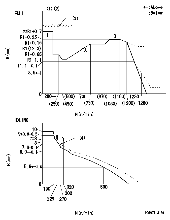
N:Pump speed
R:Rack position (mm)
(1)Torque cam stamping: T1
(2)Tolerance for racks not indicated: +-0.05mm.
(3)Stop lever's normal position setting: equivalent to RA
(4)Damper spring setting
----------
T1=AD08 RA=18mm
----------
----------
T1=AD08 RA=18mm
----------
Speed control lever angle
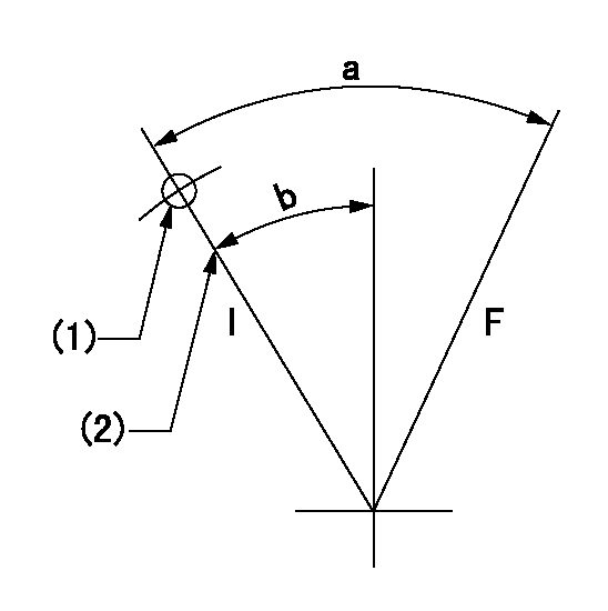
F:Full speed
I:Idle
(1)Use the hole at R = aa
(2)Stopper bolt set position 'H'
----------
aa=47mm
----------
a=33deg+-3deg b=20deg+-5deg
----------
aa=47mm
----------
a=33deg+-3deg b=20deg+-5deg
Stop lever angle
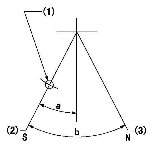
N:Pump normal
S:Stop the pump.
(1)Use the pin at R = aa
(2)Set the stopper bolt so that speed = bb and rack position = cc. (Confirm non-injection.)
(3)Set the stopper bolt so that rack position = dd.
----------
aa=40mm bb=0r/min cc=4+-0.3mm dd=18mm
----------
a=8.5deg+-5deg b=30deg+-5deg
----------
aa=40mm bb=0r/min cc=4+-0.3mm dd=18mm
----------
a=8.5deg+-5deg b=30deg+-5deg
0000001501 LEVER
Stop lever setting
When setting the stop lever after governor adjustment, confirm that rack position Ra can be obtained at full setting.
----------
Ra=R1(12.3)+0.7mm
----------
----------
Ra=R1(12.3)+0.7mm
----------
Timing setting

(1)Pump vertical direction
(2)Coupling's key groove position at No 1 cylinder's beginning of injection
(3)-
(4)-
----------
----------
a=(80deg)
----------
----------
a=(80deg)
Information:
(1) Thickness of spacer plate ... 9.970 0.025 mm (.3925 .0010 in) Thickness of spacer plate gasket ... 0.208 0.025 mm (.0082 .0010 in) For height of liner over top of spacer plate make reference to Cylinder Liner Projection.(2) Camshaft bearing bore (installed) ... 58.80 0.06 mm (2.315 .002 in) Bore in block for camshaft bearings ... 65.100 0.025 mm (2.5630 .0010 in)(3) Bore in block for main bearings (standard size) ... 96.926 0.013 mm (3.8160 .0005 in) Bore in block for main bearings 0.51 mm (.020 in) oversize ... 97.436 0.013 mm (3.8361 .0005 in)(4) Dimension from center of main bearing bore to top of cylinder block (new) ... 383.515 0.165 mm (15.099 .0064 in)(5) Dimension from center of main bearing bore to bottom of cylinder block (new) ... 153.99 0.10 mm (6.063 .004 in)(6) Torque for bolts holding bearing caps for main bearings: a. Put 2P2506 Thread Lubricant on threads and washer face.b. Tighten all bolts to ... 41 4 N m (30 3 lb ft)c. Put a mark on each bolt and cap.d. Tighten all bolts from mark ... 90 5° Install bearing caps with the part number toward the front of the engine. Be sure that the mark (number) on the bearing cap next to the bolt hole is in agreement with the mark in the cylinder block.(7) Clearance between main bearing cap and cylinder block ... 0.033 mm (.0013 in) tight to ... 0.043 mm (.0017 in) loose Main bearing cap width ... 165.095 0.020 mm (6.4998 .0008 in)Width of cylinder block for main bearing cap ... 165.100 0.018 mm (6.5000 .0007 in) (8) Piston cooling orifice.
There are holes in the bores for the main bearings, between the cylinders for piston cooling orifices. These holes must have orifices (8) installed.
(9) Distance two dowels extend from the surface of the cylinder block ... 19.8 0.5 mm (.78 .02 in)(10) Distance hollow dowel extends from the surface of the cylinder block ... 16.0 0.5 mm (.63 .02 in)(11) Depth to install two dowels below the surface of the cylinder block (apply Loctite #11358) ... 1.0 0.5 mm (.04 .02 in)(12) Distance dowels extend from the front face of the cylinder block ... 22.4 0.5 mm (.88 .02 in)(13) Distance stud extends from the front face of the cylinder block ... 15.7 0.5 mm (.62 .02 in)(14) Distance two dowels extend from the rear face of the cylinder block ... 12.7 0.5 mm (.50 .02 in)