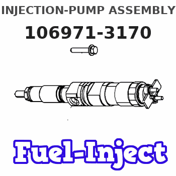
Information injection-pump assembly
BOSCH
F 019 Z10 554
f019z10554
ZEXEL
106971-3170
1069713170
HINO
220007581A
220007581a

Rating:
Service parts 106971-3170 INJECTION-PUMP ASSEMBLY:
1.
_
7.
COUPLING PLATE
8.
_
9.
_
11.
Nozzle and Holder
236002450B
12.
Open Pre:MPa(Kqf/cm2)
14.7(150)/21.6(220)
14.
NOZZLE
Include in #1:
106971-3170
as INJECTION-PUMP ASSEMBLY
Cross reference number
Zexel num
Bosch num
Firm num
Name
Information:
(1) Cylinder head bolts and nuts: 1. Put clean engine oil on the threads of bolts and nuts. Tighten bolts and nuts (cold), numbers 1 thru 32 in order shown, to a torque of 155 N m (115 lb.ft.)2. Tighten small bolts (cold), numbers 33 thru 38, to a torque of ... 38 N m (28 lb.ft.)Retighten the cylinder head bolts and nuts after the engine has run and the coolant temperature is no less than 77°C (170°F) as follows:a. If the bolts and nuts move before the correct torque (above) is reached, tighten the bolts and nuts (hot) to the torques that follow: No. 1 thru 32 ... 142 N m (105 lb.ft.)No. 33 thru 38 ... 38 N m (28 lb.ft.)b. If the bolts and nuts do not move before the correct torque is reached, back each one off 30 to 60° and retighten them again in the order shown to the torques shown in Step a. After all the bolts and nuts are retightened, check the first 10 positions again to make sure they are tightened to the correct torque.(2) Torque for nuts that hold injectors to cylinder head ... 17 N m (12 lb.ft.) Replace the copper washer and rubber seal between the head and the injector every time the injector is removed. (See Fuel Injector Installation in TESTING AND ADJUSTING.) Make sure the correct thickness washer is installed. They are as follows: 6.3544 Engines ... 2.03 mm (.080 in.)T6.3544 Engines ... 0.71 mm (.028 in.)(3) Torque for fuel line nuts ... 20 N m (15 lb.ft.)(4) Tighten rocker shaft assembly bolts and nuts from the center outward to a torque of ... 75 N m (55 lb.ft.)(5) Valve clearance (cold): Intake ... 0.20 mm (.008 in.)Exhaust ... 0.46 mm (.018 in.)(6) Maximum permissible injector nozzle projection below cylinder head face (with seating washers in position) after skimming: 6.3544 Engines ... 3.45 mm (.136 in.) max.T6.3544 Engines ... 4.67 mm (.184 in.) max.Skimming allowance ... 0.30 mm (.012 in.) max.(7) Depth of cylinder head (new) ... 94.87 to 95.63 mm (3.735 to 3.765 in.) Minimum depth of cylinder head (after skimming) ... 94.87 mm (3.735 in.)Maximum permissible amount of bow (curve of cylinder head): across width (transverse) ... 0.13 mm (.005 in.)across length (longitudinal) ... 0.25 mm (.010 in.)(See Cylinder Head Check in TESTING AND ADJUSTING)
