Information injection-pump assembly
BOSCH
F 01G 09U 0BY
f01g09u0by
ZEXEL
106971-3134
1069713134
HINO
220007324A
220007324a
Rating:
Cross reference number
BOSCH
F 01G 09U 0BY
f01g09u0by
ZEXEL
106971-3134
1069713134
HINO
220007324A
220007324a
Zexel num
Bosch num
Firm num
Name
Calibration Data:
Adjustment conditions
Test oil
1404 Test oil ISO4113 or {SAEJ967d}
1404 Test oil ISO4113 or {SAEJ967d}
Test oil temperature
degC
40
40
45
Nozzle and nozzle holder
105780-8140
Bosch type code
EF8511/9A
Nozzle
105780-0000
Bosch type code
DN12SD12T
Nozzle holder
105780-2080
Bosch type code
EF8511/9
Opening pressure
MPa
17.2
Opening pressure
kgf/cm2
175
Injection pipe
Outer diameter - inner diameter - length (mm) mm 8-3-600
Outer diameter - inner diameter - length (mm) mm 8-3-600
Overflow valve
134424-0820
Overflow valve opening pressure
kPa
127
107
147
Overflow valve opening pressure
kgf/cm2
1.3
1.1
1.5
Tester oil delivery pressure
kPa
157
157
157
Tester oil delivery pressure
kgf/cm2
1.6
1.6
1.6
Direction of rotation (viewed from drive side)
Right R
Right R
Injection timing adjustment
Direction of rotation (viewed from drive side)
Right R
Right R
Injection order
1-10-9-4
-3-6-5-8
-7-2
Pre-stroke
mm
4.8
4.74
4.8
Beginning of injection position
Governor side NO.1
Governor side NO.1
Difference between angles 1
Cal 1-10 deg. 27 26.75 27.25
Cal 1-10 deg. 27 26.75 27.25
Difference between angles 2
Cal 1-9 deg. 72 71.75 72.25
Cal 1-9 deg. 72 71.75 72.25
Difference between angles 3
Cal 1-4 deg. 99 98.75 99.25
Cal 1-4 deg. 99 98.75 99.25
Difference between angles 4
Cal 1-3 deg. 144 143.75 144.25
Cal 1-3 deg. 144 143.75 144.25
Difference between angles 5
Cal 1-6 deg. 171 170.75 171.25
Cal 1-6 deg. 171 170.75 171.25
Difference between angles 6
Cal 1-5 deg. 216 215.75 216.25
Cal 1-5 deg. 216 215.75 216.25
Difference between angles 7
Cal 1-8 deg. 243 242.75 243.25
Cal 1-8 deg. 243 242.75 243.25
Difference between angles 8
Cal 1-7 deg. 288 287.75 288.25
Cal 1-7 deg. 288 287.75 288.25
Difference between angles 9
Cyl.1-2 deg. 315 314.75 315.25
Cyl.1-2 deg. 315 314.75 315.25
Injection quantity adjustment
Adjusting point
A
Rack position
8
Pump speed
r/min
700
700
700
Average injection quantity
mm3/st.
126.4
124.4
128.4
Max. variation between cylinders
%
0
-2
2
Basic
*
Fixing the lever
*
Injection quantity adjustment_02
Adjusting point
B
Rack position
8
Pump speed
r/min
500
500
500
Average injection quantity
mm3/st.
128.4
122.4
134.4
Fixing the lever
*
Injection quantity adjustment_03
Adjusting point
C
Rack position
8.15
Pump speed
r/min
1100
1100
1100
Average injection quantity
mm3/st.
130
127
133
Fixing the lever
*
Injection quantity adjustment_04
Adjusting point
E
Rack position
4.2+-0.5
Pump speed
r/min
225
225
225
Average injection quantity
mm3/st.
10
7
13
Max. variation between cylinders
%
0
-15
15
Fixing the rack
*
Injection quantity adjustment_05
Adjusting point
F
Rack position
9.2+-0.1
Pump speed
r/min
300
300
300
Average injection quantity
mm3/st.
158
155
161
Fixing the lever
*
Injection quantity adjustment_06
Adjusting point
G
Rack position
-
Pump speed
r/min
100
100
100
Average injection quantity
mm3/st.
159
159
179
Fixing the lever
*
Timer adjustment
Pump speed
r/min
680--
Advance angle
deg.
0
0
0
Load
1/4
Remarks
Start
Start
Timer adjustment_02
Pump speed
r/min
630
Advance angle
deg.
0.3
Load
1/4
Timer adjustment_03
Pump speed
r/min
770--
Advance angle
deg.
1
0.7
1.3
Load
4/4
Timer adjustment_04
Pump speed
r/min
900+50
Advance angle
deg.
1
0.7
1.3
Load
3/4
Timer adjustment_05
Pump speed
r/min
1100-50
Advance angle
deg.
5.25
4.95
5.55
Load
4/4
Remarks
Finish
Finish
Test data Ex:
Governor adjustment
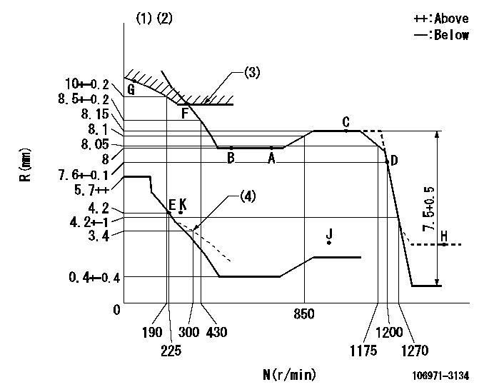
N:Pump speed
R:Rack position (mm)
(1)Tolerance for racks not indicated: +-0.05mm.
(2)Set idle at point K (N = N1, R = R1) and confirm that the injection quantity does not exceed Q1 at point J (N = N2).
(3)Excess fuel setting for starting: SXL
(4)Damper spring setting
----------
N1=325r/min R1=4.2mm N2=1150r/min Q1=3mm3/st SXL=9.2+-0.1mm
----------
----------
N1=325r/min R1=4.2mm N2=1150r/min Q1=3mm3/st SXL=9.2+-0.1mm
----------
Speed control lever angle

F:Full speed
----------
----------
a=19.5deg+-5deg
----------
----------
a=19.5deg+-5deg
0000000901

F:Full load
I:Idle
(1)Use the hole to the left of R = aa
(2)Stopper bolt setting
----------
aa=61mm
----------
a=28deg+-3deg b=17deg+-5deg
----------
aa=61mm
----------
a=28deg+-3deg b=17deg+-5deg
Stop lever angle
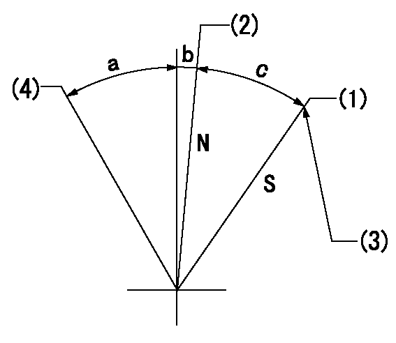
N:Engine manufacturer's normal use
S:Stop the pump.
(1)Rack position = aa
(2)Rack position bb
(3)Set the stopper bolt (apply red paint).
(4)Free (at delivery)
----------
aa=2.3-0.5mm bb=12.5mm
----------
a=(30.5deg) b=1deg+-5deg c=30deg+-5deg
----------
aa=2.3-0.5mm bb=12.5mm
----------
a=(30.5deg) b=1deg+-5deg c=30deg+-5deg
Timing setting

(1)Pump vertical direction
(2)Coupling's key groove position at No 1 cylinder's beginning of injection
(3)-
(4)-
----------
----------
a=(80deg)
----------
----------
a=(80deg)
Information:
4.236 Engines(1) First (top) compression ring: Width of compression ring ... 2.362 to 2.375 mm (.0930 to .0935 in)Clearance between ends of ring installed in cylinder liner that has no wear ... 0.25 to 0.56 mm (.010 to .022 in)(2) Second compression ring: Width of compression ring ... 2.362 to 2.375 mm (.0930 to .0935 in)Clearance between ends of each ring installed in cylinder liner that has no wear ... 0.20 to 0.56 mm (.008 to .022 in)(3) Oil ring: Width of oil ring ... 4.724 to 4.737 mm (.1860 to .1865 in)Clearance between ends of each ring installed in cylinder liner that has no wear ... 0.25 to 0.53 mm (.010 to .021 in)(4) Width of groove for first compression ring ... 2.46 to 2.49 mm (.097 to .098 in) Ring clearance in the groove ... 0.089 to 0.127 mm (.0035 to .0050 in)(5) Width of groove for second compression ring ... 2.44 to 2.46 mm (.096 to .097 in) Ring clearance in the groove ... 0.064 to 0.102 mm (.0025 to .0040 in)(6) Width of groove for oil ring ... 4.788 to 4.806 mm (.1885 to .1892 in) Ring clearance in the groove ... 0.051 to 0.081 mm (.0020 to .0032 in)(7) Bore in piston for pin ... 34.9212 to 34.9263 mm (1.37485 to 1.37505 in) Diameter of piston pin (new) ... 34.920 to 34.93 mm (1.3748 to 1.375 in)Piston height above cylinder block (not shown) ... 0.36 to 0.58 mm (.014 to .023 in)C4.236 Engines
C4.236 Engines(1) First (top) compression ring: Width of compression ring ... wedge shapedClearance between ends of ring installed in cylinder liner that has no wear ... 0.25 to 0.61 mm (.010 to .024 in)(2) Second compression ring: Width of compression ring ... 2.362 to 2.375 mm (.0930 to .0935 in)Clearance between ends of each ring installed in cylinder liner that has no wear ... 0.25 to 0.69 mm (.010 to .027 in)(3) Oil ring: Width of oil ring ... 4.724 to 4.763 mm (.1860 to .1875 in)Clearance between ends of each ring installed in cylinder liner that has no wear ... 0.25 to 0.79 mm (.010 to .031 in)(4) Width of groove for first compression ring ... tapered(5) Width of groove for second compression ring ... 2.426 to 2.446 mm (.0955 to .0963 in) Ring clearance in the groove ... 0.051 to 0.084 mm (.0020 to .0033 in)(6) Width of groove for oil ring ... 4.788 to 4.808 mm (.1885 to .1893 in) Ring clearance in the groove ... 0.025 to 0.084 mm (.0010 to .0033 in)(7) Bore in piston for pin ... 38.100 to 38.1005 mm (1.5000 to 1.50002 in) Diameter of piston pin (new) ... 38.095 to 38.100 mm (1.4998 to 1.5000 in)Piston height above cylinder block (not shown) ... 0.36 to 0.58 mm (.014 to .023 in)