Information injection-pump assembly
ZEXEL
106971-3120
1069713120
HINO
220007180A
220007180a

Rating:
Cross reference number
ZEXEL
106971-3120
1069713120
HINO
220007180A
220007180a
Zexel num
Bosch num
Firm num
Name
Calibration Data:
Adjustment conditions
Test oil
1404 Test oil ISO4113 or {SAEJ967d}
1404 Test oil ISO4113 or {SAEJ967d}
Test oil temperature
degC
40
40
45
Nozzle and nozzle holder
105780-8140
Bosch type code
EF8511/9A
Nozzle
105780-0000
Bosch type code
DN12SD12T
Nozzle holder
105780-2080
Bosch type code
EF8511/9
Opening pressure
MPa
17.2
Opening pressure
kgf/cm2
175
Injection pipe
Outer diameter - inner diameter - length (mm) mm 8-3-600
Outer diameter - inner diameter - length (mm) mm 8-3-600
Overflow valve
134424-0820
Overflow valve opening pressure
kPa
127
107
147
Overflow valve opening pressure
kgf/cm2
1.3
1.1
1.5
Tester oil delivery pressure
kPa
157
157
157
Tester oil delivery pressure
kgf/cm2
1.6
1.6
1.6
Direction of rotation (viewed from drive side)
Right R
Right R
Injection timing adjustment
Direction of rotation (viewed from drive side)
Right R
Right R
Injection order
1-10-9-4
-3-6-5-8
-7-2
Pre-stroke
mm
4.8
4.74
4.8
Beginning of injection position
Governor side NO.1
Governor side NO.1
Difference between angles 1
Cal 1-10 deg. 27 26.75 27.25
Cal 1-10 deg. 27 26.75 27.25
Difference between angles 2
Cal 1-9 deg. 72 71.75 72.25
Cal 1-9 deg. 72 71.75 72.25
Difference between angles 3
Cal 1-4 deg. 99 98.75 99.25
Cal 1-4 deg. 99 98.75 99.25
Difference between angles 4
Cal 1-3 deg. 144 143.75 144.25
Cal 1-3 deg. 144 143.75 144.25
Difference between angles 5
Cal 1-6 deg. 171 170.75 171.25
Cal 1-6 deg. 171 170.75 171.25
Difference between angles 6
Cal 1-5 deg. 216 215.75 216.25
Cal 1-5 deg. 216 215.75 216.25
Difference between angles 7
Cal 1-8 deg. 243 242.75 243.25
Cal 1-8 deg. 243 242.75 243.25
Difference between angles 8
Cal 1-7 deg. 288 287.75 288.25
Cal 1-7 deg. 288 287.75 288.25
Difference between angles 9
Cyl.1-2 deg. 315 314.75 315.25
Cyl.1-2 deg. 315 314.75 315.25
Injection quantity adjustment
Adjusting point
A
Rack position
8.5
Pump speed
r/min
700
700
700
Average injection quantity
mm3/st.
123.5
121.5
125.5
Max. variation between cylinders
%
0
-2
2
Basic
*
Fixing the lever
*
Injection quantity adjustment_02
Adjusting point
B
Rack position
8.5
Pump speed
r/min
500
500
500
Average injection quantity
mm3/st.
125.2
122.2
128.2
Fixing the lever
*
Injection quantity adjustment_03
Adjusting point
C
Rack position
8.7
Pump speed
r/min
1100
1100
1100
Average injection quantity
mm3/st.
124.4
121.4
127.4
Fixing the lever
*
Injection quantity adjustment_04
Adjusting point
E
Rack position
4.3+-0.5
Pump speed
r/min
225
225
225
Average injection quantity
mm3/st.
10.8
7.8
13.8
Max. variation between cylinders
%
0
-15
15
Fixing the rack
*
Injection quantity adjustment_05
Adjusting point
G
Rack position
-
Pump speed
r/min
100
100
100
Average injection quantity
mm3/st.
161
161
181
Fixing the lever
*
Timer adjustment
Pump speed
r/min
680--
Advance angle
deg.
0
0
0
Load
1/4
Remarks
Start
Start
Timer adjustment_02
Pump speed
r/min
630
Advance angle
deg.
0.3
Load
1/4
Timer adjustment_03
Pump speed
r/min
770--
Advance angle
deg.
1
0.7
1.3
Load
4/4
Timer adjustment_04
Pump speed
r/min
900+50
Advance angle
deg.
1
0.7
1.3
Load
3/4
Timer adjustment_05
Pump speed
r/min
1100-50
Advance angle
deg.
5.25
4.95
5.55
Load
4/4
Remarks
Finish
Finish
Test data Ex:
Governor adjustment
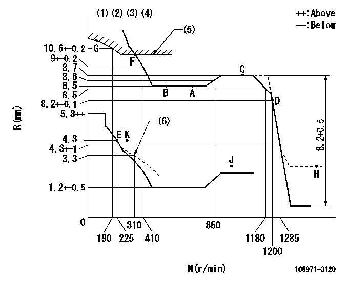
N:Pump speed
R:Rack position (mm)
(1)Lever ratio: RT
(2)Target shim dimension: TH
(3)Tolerance for racks not indicated: +-0.05mm.
(4)Set idle at point K (N = N1, R = R1) and confirm that the injection quantity does not exceed Q1 at point J (N = N2).
(5)Excess fuel setting for starting: SXL
(6)Damper spring setting
----------
RT=0.8 TH=3mm N1=300r/min R1=4.3mm N2=1000r/min Q1=3mm3/st SXL=10.1+-0.1mm
----------
----------
RT=0.8 TH=3mm N1=300r/min R1=4.3mm N2=1000r/min Q1=3mm3/st SXL=10.1+-0.1mm
----------
Speed control lever angle

F:Full speed
----------
----------
a=13.5deg+-5deg
----------
----------
a=13.5deg+-5deg
0000000901

F:Full load
I:Idle
(1)Use the hole at R = aa
(2)Stopper bolt setting
----------
aa=61mm
----------
a=39deg+-3deg b=17deg+-5deg
----------
aa=61mm
----------
a=39deg+-3deg b=17deg+-5deg
Stop lever angle
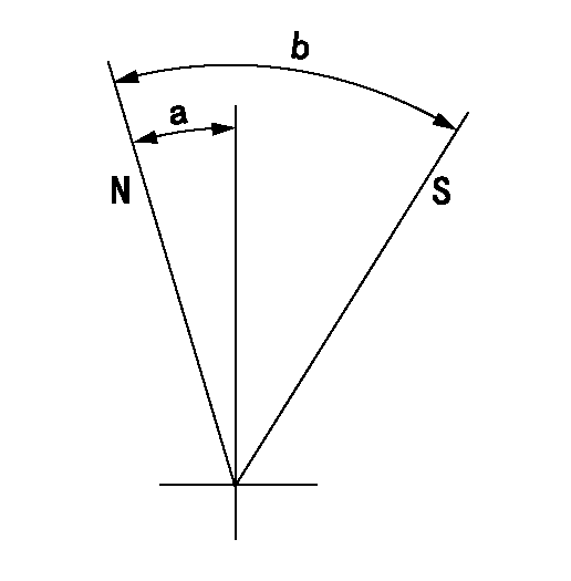
N:Pump normal
S:Stop the pump.
----------
----------
a=16deg+-5deg b=64deg+-5deg
----------
----------
a=16deg+-5deg b=64deg+-5deg
Timing setting

(1)Pump vertical direction
(2)Coupling's key groove position at No 1 cylinder's beginning of injection
(3)-
(4)-
----------
----------
a=(80deg)
----------
----------
a=(80deg)
Information:
This Revised Service Letter replaces the 05Dec2012 (Revised 31Jan2013) Service Letter. Changes have been made to the Affected Product and Action Required.
TERMINATION DATE
31Dec2013
PROBLEM
The existing fuel injector has a 150 degree spray pattern. During the combustion stroke (process), the current end of injection timing maps can allow the 150 degree spray pattern to temporarily impinge upon the exposed wall of the cylinder liner as the piston moves downward in the bore.
Depending on engine speed and load factors, the fuel making contact with the liner can dilute the oil film or cause excessive soot. The excessive soot can build up to form carbon deposits at the piston lands and grooves, resulting in uneven top ring and groove wear, which may cause ring breakage. This situation is aggravated by contamination within the air and lubrication systems.
AFFECTED PRODUCT
Model Identification Number
793D FDB00105-01737, 1739
PARTS NEEDED
Qty
Part Number Description
16 20R2296 INJECTOR GP-FUEL
1 4264383 SOFTWARE GP-ELEK
In order to allow equitable parts availability to all participating dealers, please limit your initial parts order to not exceed 7% of dealership population. This is an initial order recommendation only, and the ultimate responsibility for ordering the total number of parts needed to satisfy the program lies with the dealer.
ACTION REQUIRED
This program does not apply to 793D Off-Highway Trucks equipped with high altitude engine arrangements.
If a 793D Off-Highway Truck that is listed in the Affected Product already has 423-7547 Fuel Injectors or 20R-2296 Fuel Injectors installed, do not apply this Service Letter.
Refer to the service manual if/as necessary.
Install a full set of sixteen 145 degree fuel injectors along with the software.
NOTE 1: Do not mix the 145 degree fuel injectors with the former 150 degree fuel injectors in the same engine.
NOTE 2: Do not install the software that is listed in the Parts Needed unless all sixteen fuel injectors have been replaced by the 145 degree spray pattern fuel injectors that is listed in the Parts Needed.
SERVICE CLAIM ALLOWANCES
Product smu/age whichever comes first Caterpillar Dealer Suggested Customer Suggested
Parts % Labor Hrs% Parts % Labor Hrs% Parts % Labor Hrs%
0-1000 hrs,
0-6 mo 100.0% 100.0% 0.0% 0.0% 0.0% 0.0%
This is a 8.0-hour job
If there has been a previous repair, part age/hours will apply. Retain a copy of the previous repair invoice in the dealer's records for audit purposes, and specify repair date and machine hours in the "Additional Comments" section of the warranty claim.
If the engine is out of chassis for Planned Component Rebuild (PCR), the software and injectors should be installed. However, the costs for the software and injector update are not covered under this program.
PARTS DISPOSITION
Handle the parts in accordance with your Warranty Bulletin on warranty parts handling.