Information injection-pump assembly
ZEXEL
106971-3100
1069713100
HINO
220005621A
220005621a
Rating:
Service parts 106971-3100 INJECTION-PUMP ASSEMBLY:
1.
_
7.
COUPLING PLATE
8.
_
9.
_
11.
Nozzle and Holder
12.
Open Pre:MPa(Kqf/cm2)
14.7(150)/21.6(220)
15.
NOZZLE SET
Include in #1:
106971-3100
as INJECTION-PUMP ASSEMBLY
Cross reference number
ZEXEL
106971-3100
1069713100
HINO
220005621A
220005621a
Zexel num
Bosch num
Firm num
Name
106971-3100
220005621A HINO
INJECTION-PUMP ASSEMBLY
V21C * K
V21C * K
Calibration Data:
Adjustment conditions
Test oil
1404 Test oil ISO4113 or {SAEJ967d}
1404 Test oil ISO4113 or {SAEJ967d}
Test oil temperature
degC
40
40
45
Nozzle and nozzle holder
105780-8140
Bosch type code
EF8511/9A
Nozzle
105780-0000
Bosch type code
DN12SD12T
Nozzle holder
105780-2080
Bosch type code
EF8511/9
Opening pressure
MPa
17.2
Opening pressure
kgf/cm2
175
Injection pipe
Outer diameter - inner diameter - length (mm) mm 8-3-600
Outer diameter - inner diameter - length (mm) mm 8-3-600
Overflow valve
134424-0820
Overflow valve opening pressure
kPa
127
107
147
Overflow valve opening pressure
kgf/cm2
1.3
1.1
1.5
Tester oil delivery pressure
kPa
157
157
157
Tester oil delivery pressure
kgf/cm2
1.6
1.6
1.6
Direction of rotation (viewed from drive side)
Right R
Right R
Injection timing adjustment
Direction of rotation (viewed from drive side)
Right R
Right R
Injection order
1-10-9-4
-3-6-5-8
-7-2
Pre-stroke
mm
4.8
4.74
4.8
Beginning of injection position
Governor side NO.1
Governor side NO.1
Difference between angles 1
Cal 1-10 deg. 27 26.75 27.25
Cal 1-10 deg. 27 26.75 27.25
Difference between angles 2
Cal 1-9 deg. 72 71.75 72.25
Cal 1-9 deg. 72 71.75 72.25
Difference between angles 3
Cal 1-4 deg. 99 98.75 99.25
Cal 1-4 deg. 99 98.75 99.25
Difference between angles 4
Cal 1-3 deg. 144 143.75 144.25
Cal 1-3 deg. 144 143.75 144.25
Difference between angles 5
Cal 1-6 deg. 171 170.75 171.25
Cal 1-6 deg. 171 170.75 171.25
Difference between angles 6
Cal 1-5 deg. 216 215.75 216.25
Cal 1-5 deg. 216 215.75 216.25
Difference between angles 7
Cal 1-8 deg. 243 242.75 243.25
Cal 1-8 deg. 243 242.75 243.25
Difference between angles 8
Cal 1-7 deg. 288 287.75 288.25
Cal 1-7 deg. 288 287.75 288.25
Difference between angles 9
Cyl.1-2 deg. 315 314.75 315.25
Cyl.1-2 deg. 315 314.75 315.25
Injection quantity adjustment
Adjusting point
A
Rack position
7.5
Pump speed
r/min
700
700
700
Average injection quantity
mm3/st.
123.3
121.3
125.3
Max. variation between cylinders
%
0
-2
2
Basic
*
Fixing the lever
*
Injection quantity adjustment_02
Adjusting point
B
Rack position
7.4
Pump speed
r/min
500
500
500
Average injection quantity
mm3/st.
119.4
116.4
122.4
Max. variation between cylinders
%
0
-5
5
Fixing the lever
*
Injection quantity adjustment_03
Adjusting point
C
Rack position
7.7
Pump speed
r/min
1100
1100
1100
Average injection quantity
mm3/st.
133.7
130.7
136.7
Max. variation between cylinders
%
0
-5
5
Fixing the lever
*
Injection quantity adjustment_04
Adjusting point
E
Rack position
4.6+-0.5
Pump speed
r/min
225
225
225
Average injection quantity
mm3/st.
8
5
11
Max. variation between cylinders
%
0
-15
15
Fixing the rack
*
Injection quantity adjustment_05
Adjusting point
F
Rack position
-
Pump speed
r/min
100
100
100
Average injection quantity
mm3/st.
180
180
200
Fixing the lever
*
Rack limit
*
Timer adjustment
Pump speed
r/min
(825)
Advance angle
deg.
0
0
0
Remarks
Start
Start
Timer adjustment_02
Pump speed
r/min
1100
Advance angle
deg.
4.75
4.25
5.25
Remarks
Finish
Finish
Test data Ex:
Governor adjustment
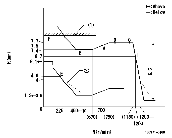
N:Pump speed
R:Rack position (mm)
(1)RACK LIMIT
(2)Damper spring setting: DL
----------
DL=3.9-0.5mm
----------
----------
DL=3.9-0.5mm
----------
Speed control lever angle

F:Full speed
----------
----------
a=15deg+-5deg
----------
----------
a=15deg+-5deg
0000000901

F:Full load
I:Idle
(1)Use the hole at R = aa
(2)Stopper bolt setting
----------
aa=61mm
----------
a=33deg+-3deg b=17deg+-5deg
----------
aa=61mm
----------
a=33deg+-3deg b=17deg+-5deg
Stop lever angle
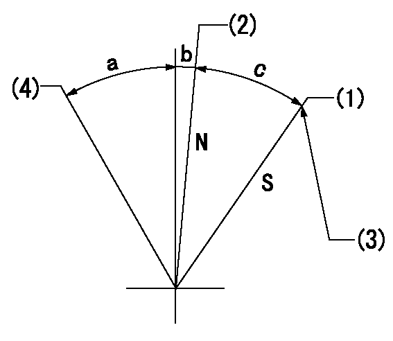
N:Engine manufacturer's normal use
S:Stop the pump.
(1)Rack position = aa
(2)Rack position bb
(3)Set the stopper bolt (apply red paint).
(4)Free (at delivery)
----------
aa=3-0.5mm bb=11.7mm
----------
a=(30deg) b=3deg+-5deg c=26deg+-5deg
----------
aa=3-0.5mm bb=11.7mm
----------
a=(30deg) b=3deg+-5deg c=26deg+-5deg
Timing setting

(1)Pump vertical direction
(2)Coupling's key groove position at No 1 cylinder's beginning of injection
(3)-
(4)-
----------
----------
a=(80deg)
----------
----------
a=(80deg)
Information:
Model Identification Number
773G JWS00162-00208
773G OEM T5T00101
775G MJS00273-00322
PARTS NEEDED
Qty
Part Number Description
2 1R1808 FILTER-LUBE
12 8S9191 BOLT
4 3460335 CLAMP-BAND
12 3594040 INJECTOR GP-FUEL
1 BULK_OIL DEO-ULS (95 Liters)
In order to allow equitable parts availability to all participating dealers, please limit your initial parts order to not exceed 4% of dealership population. This is an initial order recommendation only, and the ultimate responsibility for ordering the total number of parts needed to satisfy the program lies with the dealer.
ACTION REQUIRED
If excessive fuel dilution of engine oil is found reference the following documents to determine the cause of fuel dilution.
Special Instruction, REHS3007,"Determining the Cause of Fuel Dilution of Engine Oil"
Troubleshooting, KENR9795, "C27 and C32 Engines for Caterpillar Built Machines"
Once an injector(s) has been identified as having a cracked/leaking injector body, replace the failed injector(s). Inspect the remaining good injector serial numbers with Cat ET, (Injector Serial Numbers = Injector trim file name, (ie 6Cxxxxxxxxxx.trm)). If the remaining injector serial numbers fall within the serial number range below, replace at the same time. Refer to Image 1 for the serial number
location on the top of the electronic unit injector.
Injector Serial Numbers
6C0018656646 through 6C0021994059
If an injector failure occurs on either of the rear two cylinders (right and/or left hand bank) the exhaust piping going from the turbo to the CEM will have to be removed. 346-0335 Exhaust Clamp cannot be reused and MUST be replaced with a new clamp. Refer to REHS5014, "Reuse Guideline for the Flexible Exhaust Pipe Group on Tier 4 Engines" for the proper installation and removal procedure. Refer to Image 2 for clamp location.
The 8S-9191 Injector Hold Down Bolts must be replaced.
Refer to Disassembly and Assembly, RENR9217 for the removal, installation, and tightening procedures.
After the engine is reassembled, change the engine oil and filters.
Image1
Image2
SERVICE CLAIM ALLOWANCES
Product smu/age whichever comes first Caterpillar Dealer Suggested Customer Suggested
Parts % Labor Hrs% Parts % Labor Hrs% Parts % Labor Hrs%
0-3500 hrs,
0-24 mo 100.0% 100.0% 0.0% 0.0% 0.0% 0.0%
3501-6000 hrs,
25-48 mo 33.0% 50.0% 0.0% 0.0% 50.0% 50.0%
This is a 10.0-hour job
If there has been a previous repair, part age/hours will apply. Retain a copy of the previous repair invoice in the dealer's records for audit purposes, and specify repair date and machine hours in the "Additional Comments" section of the warranty claim.
PARTS DISPOSITION
Handle the parts in accordance with your Warranty Bulletin on warranty parts handling.
Have questions with 106971-3100?
Group cross 106971-3100 ZEXEL
Hino
106971-3100
220005621A
INJECTION-PUMP ASSEMBLY
V21C
V21C