Information injection-pump assembly
ZEXEL
106971-3082
1069713082
HINO
220005592A
220005592a
Rating:
Service parts 106971-3082 INJECTION-PUMP ASSEMBLY:
1.
_
7.
COUPLING PLATE
8.
_
9.
_
11.
Nozzle and Holder
23600-1910
12.
Open Pre:MPa(Kqf/cm2)
14.7{150}/21.6{220}
15.
NOZZLE SET
Include in #1:
106971-3082
as INJECTION-PUMP ASSEMBLY
Cross reference number
ZEXEL
106971-3082
1069713082
HINO
220005592A
220005592a
Zexel num
Bosch num
Firm num
Name
106971-3082
220005592A HINO
INJECTION-PUMP ASSEMBLY
V22C * K 14CE PE10P PE
V22C * K 14CE PE10P PE
Calibration Data:
Adjustment conditions
Test oil
1404 Test oil ISO4113 or {SAEJ967d}
1404 Test oil ISO4113 or {SAEJ967d}
Test oil temperature
degC
40
40
45
Nozzle and nozzle holder
105780-8140
Bosch type code
EF8511/9A
Nozzle
105780-0000
Bosch type code
DN12SD12T
Nozzle holder
105780-2080
Bosch type code
EF8511/9
Opening pressure
MPa
17.2
Opening pressure
kgf/cm2
175
Injection pipe
Outer diameter - inner diameter - length (mm) mm 8-3-600
Outer diameter - inner diameter - length (mm) mm 8-3-600
Overflow valve
134424-0820
Overflow valve opening pressure
kPa
127
107
147
Overflow valve opening pressure
kgf/cm2
1.3
1.1
1.5
Tester oil delivery pressure
kPa
157
157
157
Tester oil delivery pressure
kgf/cm2
1.6
1.6
1.6
Direction of rotation (viewed from drive side)
Right R
Right R
Injection timing adjustment
Direction of rotation (viewed from drive side)
Right R
Right R
Injection order
1-10-9-4
-3-6-5-8
-7-2
Pre-stroke
mm
4.8
4.74
4.8
Beginning of injection position
Governor side NO.1
Governor side NO.1
Difference between angles 1
Cal 1-10 deg. 27 26.75 27.25
Cal 1-10 deg. 27 26.75 27.25
Difference between angles 2
Cal 1-9 deg. 72 71.75 72.25
Cal 1-9 deg. 72 71.75 72.25
Difference between angles 3
Cal 1-4 deg. 99 98.75 99.25
Cal 1-4 deg. 99 98.75 99.25
Difference between angles 4
Cal 1-3 deg. 144 143.75 144.25
Cal 1-3 deg. 144 143.75 144.25
Difference between angles 5
Cal 1-6 deg. 171 170.75 171.25
Cal 1-6 deg. 171 170.75 171.25
Difference between angles 6
Cal 1-5 deg. 216 215.75 216.25
Cal 1-5 deg. 216 215.75 216.25
Difference between angles 7
Cal 1-8 deg. 243 242.75 243.25
Cal 1-8 deg. 243 242.75 243.25
Difference between angles 8
Cal 1-7 deg. 288 287.75 288.25
Cal 1-7 deg. 288 287.75 288.25
Difference between angles 9
Cyl.1-2 deg. 315 314.75 315.25
Cyl.1-2 deg. 315 314.75 315.25
Injection quantity adjustment
Adjusting point
A
Rack position
7.7
Pump speed
r/min
700
700
700
Average injection quantity
mm3/st.
127.4
125.4
129.4
Max. variation between cylinders
%
0
-2
2
Basic
*
Fixing the lever
*
Injection quantity adjustment_02
Adjusting point
B
Rack position
7.5
Pump speed
r/min
500
500
500
Average injection quantity
mm3/st.
123.1
120.1
126.1
Max. variation between cylinders
%
0
-5
5
Fixing the lever
*
Injection quantity adjustment_03
Adjusting point
C
Rack position
8
Pump speed
r/min
1100
1100
1100
Average injection quantity
mm3/st.
142
139
145
Max. variation between cylinders
%
0
-5
5
Fixing the lever
*
Injection quantity adjustment_04
Adjusting point
F
Rack position
4.6+-0.5
Pump speed
r/min
225
225
225
Average injection quantity
mm3/st.
8
5
11
Max. variation between cylinders
%
0
-15
15
Fixing the rack
*
Injection quantity adjustment_05
Adjusting point
G
Rack position
-
Pump speed
r/min
100
100
100
Average injection quantity
mm3/st.
180
180
200
Fixing the lever
*
Rack limit
*
Timer adjustment
Pump speed
r/min
(875)
Advance angle
deg.
0
0
0
Remarks
Start
Start
Timer adjustment_02
Pump speed
r/min
1100
Advance angle
deg.
4.75
4.25
5.25
Remarks
Finish
Finish
Test data Ex:
Governor adjustment
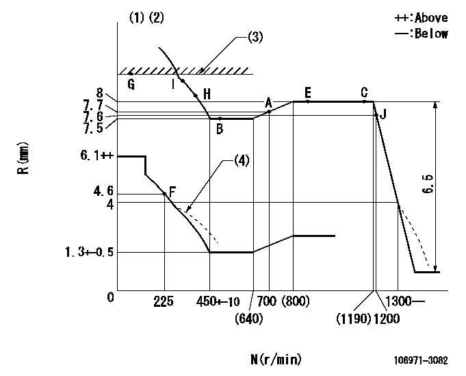
N:Pump speed
R:Rack position (mm)
(1)Lever ratio: RT
(2)Target shim dimension: TH
(3)RACK LIMIT
(4)Damper spring setting: DL
----------
RT=0.8 TH=2.4mm DL=3.9-0.5mm
----------
----------
RT=0.8 TH=2.4mm DL=3.9-0.5mm
----------
Speed control lever angle

F:Full speed
----------
----------
a=15deg+-5deg
----------
----------
a=15deg+-5deg
0000000901

F:Full load
I:Idle
(1)Use the hole at R = aa
(2)Stopper bolt setting
----------
aa=61mm
----------
a=33deg+-3deg b=17deg+-5deg
----------
aa=61mm
----------
a=33deg+-3deg b=17deg+-5deg
Stop lever angle

N:Pump normal
S:Stop the pump.
----------
----------
a=16deg+-5deg b=64deg+-5deg
----------
----------
a=16deg+-5deg b=64deg+-5deg
Timing setting

(1)Pump vertical direction
(2)Coupling's key groove position at No 1 cylinder's beginning of injection
(3)-
(4)-
----------
----------
a=(80deg)
----------
----------
a=(80deg)
Information:
PROBLEM
The front suspension A-Frame bearing may not be receiving an adequate amount of grease on machines that are equipped with the factory fitted Automatic Lubrication System. An inadequate amount of grease supply to the bearing does not promote purging of grease through the joint, especially in severe applications. This may result in premature wear of the bearing.
A larger sized injector is available which increases the amount of grease that is supplied to the bearing
Note: This service letter covers machines with factory fitted Automatic Lubrication Systems only. Dealer installed Automatic Lubrications Systems are not covered.
AFFECTED PRODUCT
Model Identification Number
735B L4D00368, 372, 375-380, 384-403
T4P00253-00258, 268-271, 275-277, 280-282, 284-286, 290-292, 302, 304
740B L4E00374-00378, 380, 385, 390, 392-393, 401-403, 407-408, 411, 419, 429-430, 433-437, 440, 443-449, 451, 453-455, 459, 465, 469, 471, 478, 480, 489, 492, 505, 511, 517, 522-529, 533, 535, 543, 549-550, 558, 560, 563, 567, 570, 575-576, 584, 592, 609-610, 612-616, 622, 624-627, 633-634, 643, 666, 670-673, 679-682, 687-694, 701-702, 708, 710, 712, 715-716, 722, 726-728, 734-735, 738, 741-743, 745-746, 755-757, 760, 763, 768, 774, 777, 779, 784-785, 788-789, 792, 796-799, 802-803, 805, 810, 812-813, 816-817, 821-822, 826-828, 833, 837, 842, 851, 853, 857, 861, 865-867, 881-882, 885, 887, 890-891, 896, 900, 903-904, 909-910, 912-915, 917-919, 921, 924-925, 927, 932-933, 945-950, 955-957, 962-971, 976-980, 985
T4R00267-00273, 278, 282-283, 289, 294, 299-300, 309-310, 322-323, 327, 339, 342, 348, 352, 354, 356, 359-360, 362-369, 371, 376-377, 393, 406, 423, 427, 431-432, 450, 518, 539-540, 543-546, 550, 557, 568, 581-582, 587-590
740B EJ L4F00383-00388
T4S00272-00274, 276-279, 282, 289-290, 296-299, 301, 304-309, 311
PARTS NEEDED
Qty
Part Number Description
1 1926212 INJECTOR
In order to allow equitable parts availability to all participating dealers, please limit your initial parts order to not exceed 16% of dealership population. This is an initial order recommendation only, and the ultimate responsibility for ordering the total number of parts needed to satisfy the program lies with the dealer.
ACTION REQUIRED
See attached rework procedure.
SERVICE CLAIM ALLOWANCES
Product smu/age whichever comes first Caterpillar Dealer Suggested Customer Suggested
Parts % Labor Hrs% Parts % Labor Hrs% Parts % Labor Hrs%
0-8000 hrs,
0-48 mo 100.0% 100.0% 0.0% 0.0% 0.0% 0.0%
This is a 0.5-hour job
PARTS DISPOSITION
Handle the parts in accordance with your Warranty Bulletin on warranty parts handling.
Rework Procedure
(1). Remove the grease injector from the manifold that is located on the right side of the front chassis. See Image 1.1.1 for location.
(2). Install new 192-6212 Injector.
(3). Purge new injector by pressing the Test Switch on the Auto Lube pump. See Image 1.1.2 for test switch location.
(4). Install the grease line to the injector.
Image1.1.1
Image1.1.2
Have questions with 106971-3082?
Group cross 106971-3082 ZEXEL
Hino
106971-3082
220005592A
INJECTION-PUMP ASSEMBLY
V22C
V22C