Information injection-pump assembly
ZEXEL
106971-3070
1069713070
HINO
220004281A
220004281a

Rating:
Cross reference number
ZEXEL
106971-3070
1069713070
HINO
220004281A
220004281a
Zexel num
Bosch num
Firm num
Name
Calibration Data:
Adjustment conditions
Test oil
1404 Test oil ISO4113 or {SAEJ967d}
1404 Test oil ISO4113 or {SAEJ967d}
Test oil temperature
degC
40
40
45
Nozzle and nozzle holder
105780-8140
Bosch type code
EF8511/9A
Nozzle
105780-0000
Bosch type code
DN12SD12T
Nozzle holder
105780-2080
Bosch type code
EF8511/9
Opening pressure
MPa
17.2
Opening pressure
kgf/cm2
175
Injection pipe
Outer diameter - inner diameter - length (mm) mm 8-3-600
Outer diameter - inner diameter - length (mm) mm 8-3-600
Overflow valve
134424-0820
Overflow valve opening pressure
kPa
127
107
147
Overflow valve opening pressure
kgf/cm2
1.3
1.1
1.5
Tester oil delivery pressure
kPa
157
157
157
Tester oil delivery pressure
kgf/cm2
1.6
1.6
1.6
Direction of rotation (viewed from drive side)
Right R
Right R
Injection timing adjustment
Direction of rotation (viewed from drive side)
Right R
Right R
Injection order
1-10-9-4
-3-6-5-8
-7-2
Pre-stroke
mm
4
3.94
4
Beginning of injection position
Governor side NO.1
Governor side NO.1
Difference between angles 1
Cal 1-10 deg. 27 26.75 27.25
Cal 1-10 deg. 27 26.75 27.25
Difference between angles 2
Cal 1-9 deg. 72 71.75 72.25
Cal 1-9 deg. 72 71.75 72.25
Difference between angles 3
Cal 1-4 deg. 99 98.75 99.25
Cal 1-4 deg. 99 98.75 99.25
Difference between angles 4
Cal 1-3 deg. 144 143.75 144.25
Cal 1-3 deg. 144 143.75 144.25
Difference between angles 5
Cal 1-6 deg. 171 170.75 171.25
Cal 1-6 deg. 171 170.75 171.25
Difference between angles 6
Cal 1-5 deg. 216 215.75 216.25
Cal 1-5 deg. 216 215.75 216.25
Difference between angles 7
Cal 1-8 deg. 243 242.75 243.25
Cal 1-8 deg. 243 242.75 243.25
Difference between angles 8
Cal 1-7 deg. 288 287.75 288.25
Cal 1-7 deg. 288 287.75 288.25
Difference between angles 9
Cyl.1-2 deg. 315 314.75 315.25
Cyl.1-2 deg. 315 314.75 315.25
Injection quantity adjustment
Adjusting point
A
Rack position
9.5
Pump speed
r/min
700
700
700
Average injection quantity
mm3/st.
124
122
126
Max. variation between cylinders
%
0
-2
2
Basic
*
Fixing the lever
*
Injection quantity adjustment_02
Adjusting point
B
Rack position
9.1
Pump speed
r/min
500
500
500
Average injection quantity
mm3/st.
113
110
116
Max. variation between cylinders
%
0
-5
5
Fixing the lever
*
Injection quantity adjustment_03
Adjusting point
C
Rack position
10.2
Pump speed
r/min
1200
1200
1200
Average injection quantity
mm3/st.
148
142
154
Max. variation between cylinders
%
0
-5
5
Fixing the lever
*
Injection quantity adjustment_04
Adjusting point
H
Rack position
12.6+-0.
5
Pump speed
r/min
100
100
100
Average injection quantity
mm3/st.
160
160
180
Fixing the lever
*
Rack limit
*
Injection quantity adjustment_05
Adjusting point
I
Rack position
6.4+-0.5
Pump speed
r/min
225
225
225
Average injection quantity
mm3/st.
11
8
14
Max. variation between cylinders
%
0
-15
15
Fixing the rack
*
Timer adjustment
Pump speed
r/min
950
Advance angle
deg.
0.75
0.75
0.75
Timer adjustment_02
Pump speed
r/min
1200
Advance angle
deg.
4.25
3.95
4.55
Remarks
Finish
Finish
Test data Ex:
Governor adjustment
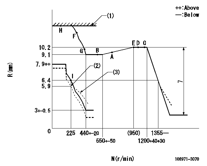
N:Pump speed
R:Rack position (mm)
(1)RACK LIMIT
(2)Set the lever at delivery.
(3)Damper spring setting: DL
----------
DL=4.4-0.2mm
----------
----------
DL=4.4-0.2mm
----------
Speed control lever angle

F:Full speed
----------
----------
a=17deg+-5deg
----------
----------
a=17deg+-5deg
0000000901
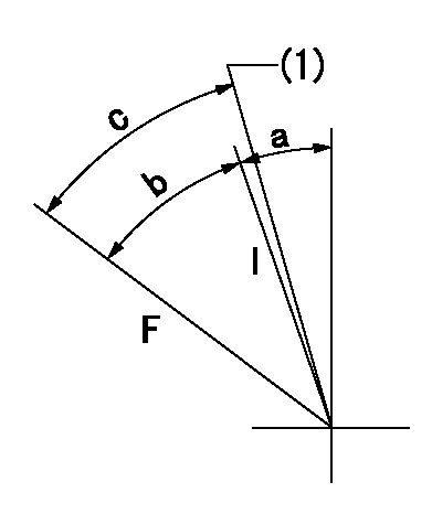
F:Full load
I:Idle
(1)Set the lever at delivery (set the stopper bolt).
----------
----------
a=22deg+-5deg b=32deg+-3deg c=35deg+-3deg
----------
----------
a=22deg+-5deg b=32deg+-3deg c=35deg+-3deg
Stop lever angle
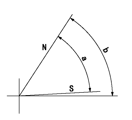
N:Pump normal
S:Stop the pump.
----------
----------
a=64deg+-5deg b=64deg+-5deg
----------
----------
a=64deg+-5deg b=64deg+-5deg
Timing setting

(1)Pump vertical direction
(2)Coupling's key groove position at No 1 cylinder's beginning of injection
(3)-
(4)-
----------
----------
a=(90deg)
----------
----------
a=(90deg)
Information:
start by:a) disassemble governorb) remove fuel injection pumps 1. Remove cover (1) from the fuel injection pump housing. 2. Remove rack (2) from the fuel injection pump housing. 3. Remove the lifters (3) from the fuel injection pump housing. 4. Put the fuel injection pump housing on end on blocks and use tool (A) to remove snap ring (4) from the camshaft. 5. Use a soft hammer to push the camshaft toward the governor end of the fuel injection pump housing to loosen washer (5) on the camshaft. Remove washer (5). 6. Remove camshaft (6) from the fuel injection pump housing. 7. Remove bearings (7) from the drive end of the fuel injection pump housing. 8. Remove bearings (8) from the governor end of the fuel injection pump housing.Assemble Fuel Injection Pump Housing
Be sure all oil passages are clear and put clean oil on all parts before assembly. 1. Use tooling (A) to install bearing (2) in the governor end of the fuel injection pump housing with junction (joint) (3) toward the top of the fuel injection pump housing. Install the bearing so it is 0.25 0.20 mm (0.10 0.008 in.) below the surface of the housing.2. Use tooling (A) to install bearing (1) in the governor end of the fuel injection pump housing so it is 7.16 0.13 mm (0.282 0.005 in.) below the surface of the housing. 3. Use tooling (A) to install bearing (4) in the drive end of the fuel injection pump housing with the junction (joint) in the bearing toward the top of the fuel injection pump housing. Install the bearing so it is 1.00 0.25 mm (0.039 0.010 in.) below the surface of the housing. 4. Install plate (6) of tooling (C) on the drive end of the fuel injection pump housing to install the bearing for the rack. Use clean grease to hold the new rack bearing on driver (5) of tooling (C). Install the driver and bearing in plate (6) with the groove in the driver in alignment with the pin in the plate and use a hammer to push the bearing into position. The bearing will be installed to the correct depth when the shoulder of the driver is against plate (6).5. Remove tooling (C) from the fuel injection pump housing. The rack bearing must be installed so it is 0.25 0.25 mm (0.010 0.010 in.) below the surface of the housing. 6. Install camshaft (7) in the fuel injection pump housing.7. Put the fuel injection pump housing on end and put a block under the camshaft. 8. Put washer (9) over the end of the camshaft and use tooling (A) and a spacer (8) that has an inside diameter of 38.1 mm (1.5 in.) and a length of 31.75 mm (1.25 in.) to push the washer against its seat on the camshaft. Camshaft must have 0.285 0.235 mm (0.0112 0.0093 in.) end play when washer is pushed against
Be sure all oil passages are clear and put clean oil on all parts before assembly. 1. Use tooling (A) to install bearing (2) in the governor end of the fuel injection pump housing with junction (joint) (3) toward the top of the fuel injection pump housing. Install the bearing so it is 0.25 0.20 mm (0.10 0.008 in.) below the surface of the housing.2. Use tooling (A) to install bearing (1) in the governor end of the fuel injection pump housing so it is 7.16 0.13 mm (0.282 0.005 in.) below the surface of the housing. 3. Use tooling (A) to install bearing (4) in the drive end of the fuel injection pump housing with the junction (joint) in the bearing toward the top of the fuel injection pump housing. Install the bearing so it is 1.00 0.25 mm (0.039 0.010 in.) below the surface of the housing. 4. Install plate (6) of tooling (C) on the drive end of the fuel injection pump housing to install the bearing for the rack. Use clean grease to hold the new rack bearing on driver (5) of tooling (C). Install the driver and bearing in plate (6) with the groove in the driver in alignment with the pin in the plate and use a hammer to push the bearing into position. The bearing will be installed to the correct depth when the shoulder of the driver is against plate (6).5. Remove tooling (C) from the fuel injection pump housing. The rack bearing must be installed so it is 0.25 0.25 mm (0.010 0.010 in.) below the surface of the housing. 6. Install camshaft (7) in the fuel injection pump housing.7. Put the fuel injection pump housing on end and put a block under the camshaft. 8. Put washer (9) over the end of the camshaft and use tooling (A) and a spacer (8) that has an inside diameter of 38.1 mm (1.5 in.) and a length of 31.75 mm (1.25 in.) to push the washer against its seat on the camshaft. Camshaft must have 0.285 0.235 mm (0.0112 0.0093 in.) end play when washer is pushed against