Information injection-pump assembly
BOSCH
9 400 618 684
9400618684
ZEXEL
106971-2063
1069712063
MITSUBISHI
ME091900
me091900
Rating:
Service parts 106971-2063 INJECTION-PUMP ASSEMBLY:
1.
_
7.
COUPLING PLATE
8.
_
9.
_
11.
Nozzle and Holder
ME091276
12.
Open Pre:MPa(Kqf/cm2)
17.7{180}/21.6{220}

15.
NOZZLE SET
Include in #1:
106971-2063
as INJECTION-PUMP ASSEMBLY
Cross reference number
BOSCH
9 400 618 684
9400618684
ZEXEL
106971-2063
1069712063
MITSUBISHI
ME091900
me091900
Zexel num
Bosch num
Firm num
Name
106971-2063
9 400 618 684
ME091900 MITSUBISHI
INJECTION-PUMP ASSEMBLY
10DC11 * K
10DC11 * K
Calibration Data:
Adjustment conditions
Test oil
1404 Test oil ISO4113 or {SAEJ967d}
1404 Test oil ISO4113 or {SAEJ967d}
Test oil temperature
degC
40
40
45
Nozzle and nozzle holder
105780-8140
Bosch type code
EF8511/9A
Nozzle
105780-0000
Bosch type code
DN12SD12T
Nozzle holder
105780-2080
Bosch type code
EF8511/9
Opening pressure
MPa
17.2
Opening pressure
kgf/cm2
175
Injection pipe
Outer diameter - inner diameter - length (mm) mm 8-3-600
Outer diameter - inner diameter - length (mm) mm 8-3-600
Overflow valve
131424-4620
Overflow valve opening pressure
kPa
255
221
289
Overflow valve opening pressure
kgf/cm2
2.6
2.25
2.95
Tester oil delivery pressure
kPa
157
157
157
Tester oil delivery pressure
kgf/cm2
1.6
1.6
1.6
Direction of rotation (viewed from drive side)
Right R
Right R
Injection timing adjustment
Direction of rotation (viewed from drive side)
Right R
Right R
Injection order
1-2-7-8-
5-6-3-4-
9-10
Pre-stroke
mm
4.8
4.75
4.85
Beginning of injection position
Governor side NO.1
Governor side NO.1
Difference between angles 1
Cyl.1-2 deg. 45 44.5 45.5
Cyl.1-2 deg. 45 44.5 45.5
Difference between angles 2
Cal 1-7 deg. 72 71.5 72.5
Cal 1-7 deg. 72 71.5 72.5
Difference between angles 3
Cal 1-8 deg. 117 116.5 117.5
Cal 1-8 deg. 117 116.5 117.5
Difference between angles 4
Cal 1-5 deg. 144 143.5 144.5
Cal 1-5 deg. 144 143.5 144.5
Difference between angles 5
Cal 1-6 deg. 189 188.5 189.5
Cal 1-6 deg. 189 188.5 189.5
Difference between angles 6
Cal 1-3 deg. 216 215.5 216.5
Cal 1-3 deg. 216 215.5 216.5
Difference between angles 7
Cal 1-4 deg. 261 260.5 261.5
Cal 1-4 deg. 261 260.5 261.5
Difference between angles 8
Cal 1-9 deg. 288 287.5 288.5
Cal 1-9 deg. 288 287.5 288.5
Difference between angles 9
Cal 1-10 deg. 333 332.5 333.5
Cal 1-10 deg. 333 332.5 333.5
Injection quantity adjustment
Adjusting point
-
Rack position
10.7
Pump speed
r/min
650
650
650
Each cylinder's injection qty
mm3/st.
130
126.1
133.9
Basic
*
Fixing the rack
*
Standard for adjustment of the maximum variation between cylinders
*
Injection quantity adjustment_02
Adjusting point
C
Rack position
6.6+-0.5
Pump speed
r/min
225
225
225
Each cylinder's injection qty
mm3/st.
17
14.4
19.6
Fixing the rack
*
Standard for adjustment of the maximum variation between cylinders
*
Injection quantity adjustment_03
Adjusting point
A
Rack position
R1(10.7)
Pump speed
r/min
650
650
650
Average injection quantity
mm3/st.
130
129
131
Basic
*
Fixing the lever
*
Injection quantity adjustment_04
Adjusting point
B
Rack position
R1(10.7)
Pump speed
r/min
1100
1100
1100
Average injection quantity
mm3/st.
131.5
127.5
135.5
Fixing the lever
*
Injection quantity adjustment_05
Adjusting point
D
Rack position
11.4+-0.
1
Pump speed
r/min
340
340
340
Average injection quantity
mm3/st.
133
129
137
Fixing the lever
*
Remarks
Startup boost setting
Startup boost setting
Injection quantity adjustment_06
Adjusting point
E
Rack position
-
Pump speed
r/min
100
100
100
Average injection quantity
mm3/st.
155
135
175
Fixing the lever
*
Remarks
After startup boost setting
After startup boost setting
Timer adjustment
Pump speed
r/min
(750)
Advance angle
deg.
0
0
0
Remarks
Start
Start
Timer adjustment_02
Pump speed
r/min
1100
Advance angle
deg.
5
4.5
5.5
Remarks
Finish
Finish
Test data Ex:
Governor adjustment
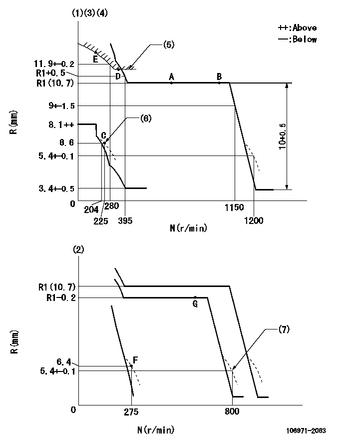
N:Pump speed
R:Rack position (mm)
(1)Adjust with speed control lever at full position (minimum-maximum speed specification)
(2)Adjust with the load control lever in the full position (variable speed specification).
(3)Tolerance for racks not indicated: +-0.05mm.
(4)Deliver without the torque control spring operating.
(5)Excess fuel setting for starting: SXL (N = N1)
(6)Damper spring setting
(7)When air cylinder is operating.
----------
SXL=11.4+-0.1mm N1=340r/min
----------
----------
SXL=11.4+-0.1mm N1=340r/min
----------
Speed control lever angle
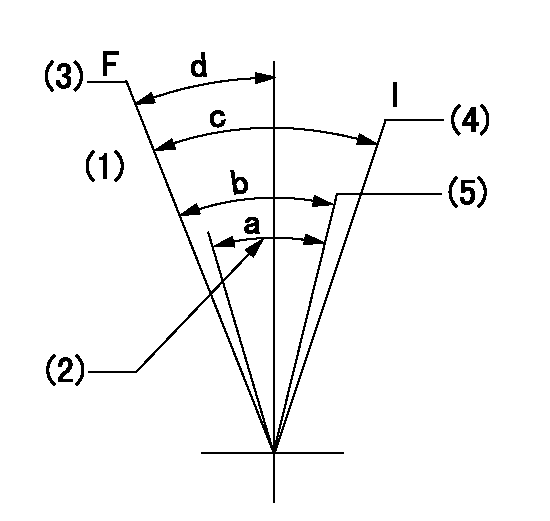
F:Full speed
I:Idle
(1)-
(2)Air cylinder's adjustable range
(3)Pump speed = aa
(4)Pump speed = bb
(5)Pump speed cc
----------
aa=1200r/min bb=275r/min cc=800r/min
----------
a=(11deg) b=(11deg)+-5deg c=(22deg)+-5deg d=(7deg)+-5deg
----------
aa=1200r/min bb=275r/min cc=800r/min
----------
a=(11deg) b=(11deg)+-5deg c=(22deg)+-5deg d=(7deg)+-5deg
0000000901

F:Full load
I:Idle
(1)Stopper bolt setting
----------
----------
a=10deg+-5deg b=27deg+-3deg
----------
----------
a=10deg+-5deg b=27deg+-3deg
Stop lever angle
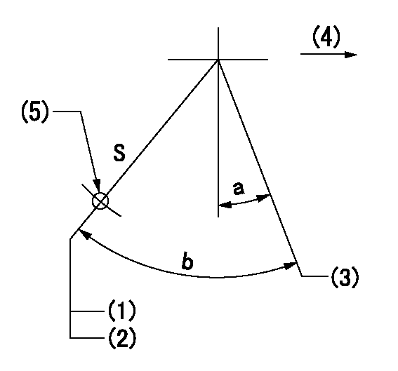
S:Stop the pump.
(1)Rack position = aa
(2)Stopper bolt setting
(3)Free (at delivery)
(4)Drive side
(5)Use the hole at R = bb
----------
aa=3.7-0.5mm bb=35mm
----------
a=10.5deg+-5deg b=57deg+7deg-5deg
----------
aa=3.7-0.5mm bb=35mm
----------
a=10.5deg+-5deg b=57deg+7deg-5deg
0000001501 2-STAGE CHANGEOVER DEVICE

RFD governor 2 stage changeover mechanism adjustment outline
(A) Bolt
(B) bolt
(c) Nut
(D) Return spring
(E) Bolt
(F) Bolt
(G) Screw
(H) Bolt
(I) Load lever
(J) Speed lever
(K) Air cylinder
(M Air inlet
Figure 1 is only for reference. Lever shape, etc, may vary.
1. Minimum-maximum speed specification adjustment (when running)
(a) Without applying air to the air cylinder, loosen bolts (A) and (B).
(1)High speed return L setting
(a) In the speed range Nf~Nf - 300r/min, adjust using the speed adjusting bolt to determine the temporary beginning of high speed control speed.
(b) Determine the rack position in the vicinity of Rf using the full load lever.
(c) Increase speed and confirm return distance L.
(d) Adjust using the tension lever bolt to obtain L.
(2)Setting full load rack position Rf
(a) Move the load control lever to the full side.
(b) Adjust the full load adjusting bolt so that Rf can be obtained, then fix.
(3)Setting the beginning of high speed operation Nf
(a) Adjust using bolt (E) so that Nf can be obtained, and then fix.
(4)Idle control setting (Re, Ni, Rc)
(a) Set the speed at Ns + 200r/min and move the load control lever to the idle side.
(b) Fix the lever in the position where Re can be obtained.
(c) Next, decrease speed to Ni and screw in the idle spring.
(d) Adjust to obtain rack position Ri.
(e) Increase the speed and after confirming that the rack position is Re at Ns, set the speed at 0.
(f) Confirm protrusion position Rc at idle.
(5)Damper spring adjustment
(a) Increase speed and set the speed at the rack position Rd - 0.1 mm
(b) Set using the damper spring so that the rack position Rd can be obtained.
(c) When Rd is not specified, Rd = Ri - 0.5 mm.
(6)High speed droop confirmation
(a) Return the load control lever to the full load lever position.
(b) Increase the speed and confirm that Rf can be obtained at Nf r/min.
(c) Confirm that speed is Nh at rack position Rh.
2. Variable speed specification adjustment (at operation)
(a) Remove return spring (D).
(b) Apply air pressure of 245~294 kPa {2.5~3 kg/cm2} to the air cylinder.
(c) Perform the following adjustment in this condition.
(1)Setting full load rack position Rf'
(a) Pull the load lever to the idle side.
(b) Obtain rack position Rf' using the nut (C). (Pump speed is Nf'-50 r/min.)
(2)Setting full speed Nf'
(a) Adjust using bolt (B) so that Nf can be obtained, and then fix.
(3)Low speed side setting
(a) At 350r/min, set bolt (F) at beginning of governor operation position, then fix.
3. Bolt (A) adjustment
(1)Install return spring (D) and perform the adjustments below at air pressure 0.
(a) Set at speed Nf using bolt (E).
(b) Screw in bolt (A).
(c) Screw in 1 more turn from the speed lever contact position
(d) Fix bolt (A).
(e) At this time confirm that the air cylinder's shaft moves approximately 1 mm towards the governor.
4. Lever operation confirmation using the air cylinder
(1)Apply 588 kPa {6 kg/cm2} air pressure to the air cylinder.
(2)Confirm that the cylinder piston is moved 50 mm by the spring (D).
----------
----------
----------
----------
0000001601 MICRO SWITCH
Adjustment of the micro-switch
Adjust the bolt to obtain the following lever position when the micro-switch is ON.
(1)Speed N1
(2)Rack position Ra
----------
N1=325r/min Ra=5.7+-0.1mm
----------
----------
N1=325r/min Ra=5.7+-0.1mm
----------
Timing setting

(1)Pump vertical direction
(2)Coupling's key groove position at No 1 cylinder's beginning of injection
(3)-
(4)-
----------
----------
a=(40deg)
----------
----------
a=(40deg)
Information:
Camshaft
When reconditioning an engine, check the diameter of the camshaft bearing journals and the camshaft lobe height.Camshaft bearing journals have a diameter of 2.5000 .0005 in. (63.500 0.013 mm) and the minimum diameter worn is 2.4970 in. (63.424 mm).To find lobe lift (A) of camshaft, use the following procedure:1. Measure lobe height (B) of one exhaust and one intake lobe.2. Measure base circle (C) of one exhaust and one intake lobe.3. Subtract base circle (C) dimension (STEP 2) from lobe height (B) dimension (STEP 1). The difference is actual lobe lift (A).4. The specified (new) lobe lift (A) is: (a) Exhaust lobe ... .3071 in.(7.800 mm)(b) Intake lobe ... .3077 in.(7.816 mm)5. The maximum permissible difference between actual lobe lift (STEP 3) and specified lobe lift (STEP 4) is .025 in. (0.64 mm).
CAMSHAFT LOBE
A. Lobe lift. B. Lobe height. C. Base circle.With camshaft installed in the cylinder block, check end play. End play with new components should be .007 .003 in. (0.18 0.08 mm). The maximum permissible end play is .020 in. (0.51 mm).Camshaft Followers
Use an 8S2293 Magnet to remove the cam followers.
REMOVING CAM FOLLOWERSCam followers establish a wear pattern with the camshaft lobes. Identify and reinstall the followers removed. Dishing or circular wear pattern is allowed on the cam follower face, providing the wear face keeps a polished appearance. Replace the follower if the wear face is rough or shows signs of scuffing. A new follower can be used with an old camshaft, providing the lobe is in good condition. Put engine oil on the cam followers and the camshaft lobes before installing the cam followers. Use new cam followers with a new camshaft.Camshaft Gears
1. Remove screw (1) and washer (2) from end of camshaft.
REMOVING TIMING ADVANCE RETAINING SCREW
1. Screw. 2. Washer.2. Remove timing advance unit from the camshaft.3. Install puller (A), with spacer (C) over the shaft in the camshaft spacer (B) on spacer (C) as shown and remove the gear from the camshaft.
REMOVING GEAR (Typical Example)
A. 1P2321 Puller. B. 8S5579 Spacer. C. 9S9155 Spacer.To install the gear use the following procedure:1. Heat the gear to a temperature of approximately 400°F (204°C) before installing on the camshaft.
Do not heat the gear with a torch. Do not heat the gear to a temperature of more than 600°F (315°C). Heating the gear with a torch or to a temperature of more than 600°F (315°C) may cause the two drive dowels for the automatic timing advance to loosen and come out of the gear.
2. Align slot in gear hub with the pin in the camshaft. Install the gear on the camshaft with timing mark on gear aligned with timing mark on crankshaft gear. Be sure the gear is completly seated against the shoulder of the camshaft.
Do not drive the gear on the camshaft.
3. Align holes in weights with dowels in gear and install the automatic timing advance.4. Align pin (3) in washer with hole (4) in camshaft and install washer (2).5. Install screw (1) and
Have questions with 106971-2063?
Group cross 106971-2063 ZEXEL
Mitsubishi
Mitsubishi
Mitsubishi
Mitsubishi
106971-2063
9 400 618 684
ME091900
INJECTION-PUMP ASSEMBLY
10DC11
10DC11