Information injection-pump assembly
BOSCH
9 400 611 290
9400611290
ZEXEL
106971-1230
1069711230
ISUZU
1156033700
1156033700
Rating:
Service parts 106971-1230 INJECTION-PUMP ASSEMBLY:
1.
_
6.
COUPLING PLATE
7.
COUPLING PLATE
8.
_
9.
_
11.
Nozzle and Holder
1-15300-328-0
12.
Open Pre:MPa(Kqf/cm2)
15.7{160}/22.1{225}
15.
NOZZLE SET
Include in #1:
106971-1230
as INJECTION-PUMP ASSEMBLY
Cross reference number
BOSCH
9 400 611 290
9400611290
ZEXEL
106971-1230
1069711230
ISUZU
1156033700
1156033700
Zexel num
Bosch num
Firm num
Name
Calibration Data:
Adjustment conditions
Test oil
1404 Test oil ISO4113 or {SAEJ967d}
1404 Test oil ISO4113 or {SAEJ967d}
Test oil temperature
degC
40
40
45
Nozzle and nozzle holder
105780-8250
Bosch type code
1 688 901 101
Nozzle
105780-0120
Bosch type code
1 688 901 990
Nozzle holder
105780-2190
Opening pressure
MPa
20.7
Opening pressure
kgf/cm2
211
Injection pipe
Outer diameter - inner diameter - length (mm) mm 8-3-600
Outer diameter - inner diameter - length (mm) mm 8-3-600
Overflow valve
134424-4320
Overflow valve opening pressure
kPa
255
221
289
Overflow valve opening pressure
kgf/cm2
2.6
2.25
2.95
Tester oil delivery pressure
kPa
255
255
255
Tester oil delivery pressure
kgf/cm2
2.6
2.6
2.6
Direction of rotation (viewed from drive side)
Right R
Right R
Injection timing adjustment
Direction of rotation (viewed from drive side)
Right R
Right R
Injection order
1-8-7-6-
5-4-3-10
-9-2
Pre-stroke
mm
5.5
5.47
5.53
Rack position
Point A R=A
Point A R=A
Beginning of injection position
Governor side NO.1
Governor side NO.1
Difference between angles 1
Cal 1-8 deg. 27 26.75 27.25
Cal 1-8 deg. 27 26.75 27.25
Difference between angles 2
Cal 1-7 deg. 72 71.75 72.25
Cal 1-7 deg. 72 71.75 72.25
Difference between angles 3
Cal 1-6 deg. 99 98.75 99.25
Cal 1-6 deg. 99 98.75 99.25
Difference between angles 4
Cal 1-5 deg. 144 143.75 144.25
Cal 1-5 deg. 144 143.75 144.25
Difference between angles 5
Cal 1-4 deg. 171 170.75 171.25
Cal 1-4 deg. 171 170.75 171.25
Difference between angles 6
Cal 1-3 deg. 216 215.75 216.25
Cal 1-3 deg. 216 215.75 216.25
Difference between angles 7
Cal 1-10 deg. 243 242.75 243.25
Cal 1-10 deg. 243 242.75 243.25
Difference between angles 8
Cal 1-9 deg. 288 287.75 288.25
Cal 1-9 deg. 288 287.75 288.25
Difference between angles 9
Cyl.1-2 deg. 315 314.75 315.25
Cyl.1-2 deg. 315 314.75 315.25
Injection quantity adjustment
Adjusting point
-
Rack position
11.1
Pump speed
r/min
800
800
800
Average injection quantity
mm3/st.
122
120.4
123.6
Max. variation between cylinders
%
0
-3
3
Basic
*
Fixing the rack
*
Standard for adjustment of the maximum variation between cylinders
*
Injection quantity adjustment_02
Adjusting point
Z
Rack position
6.7+-0.5
Pump speed
r/min
420
420
420
Average injection quantity
mm3/st.
13.5
11.5
15.5
Max. variation between cylinders
%
0
-13
13
Fixing the rack
*
Standard for adjustment of the maximum variation between cylinders
*
Injection quantity adjustment_03
Adjusting point
A
Rack position
R1(11.1)
Pump speed
r/min
800
800
800
Average injection quantity
mm3/st.
122
121
123
Basic
*
Fixing the lever
*
Injection quantity adjustment_04
Adjusting point
B
Rack position
R1+1.5
Pump speed
r/min
1150
1150
1150
Average injection quantity
mm3/st.
133
129
137
Fixing the lever
*
Timer adjustment
Pump speed
r/min
500--
Advance angle
deg.
0
0
0
Remarks
Start
Start
Timer adjustment_02
Pump speed
r/min
450
Advance angle
deg.
0.3
Timer adjustment_03
Pump speed
r/min
700
Advance angle
deg.
2
1.5
2.5
Remarks
Finish
Finish
Test data Ex:
Governor adjustment
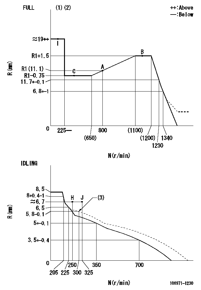
N:Pump speed
R:Rack position (mm)
(1)Torque cam stamping: T1
(2)Tolerance for racks not indicated: +-0.05mm.
(3)Damper spring setting
----------
T1=AD98
----------
----------
T1=AD98
----------
Speed control lever angle
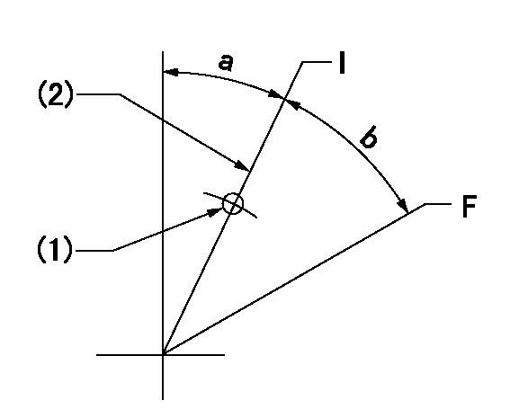
F:Full speed
I:Idle
(1)Use the pin at R = aa
(2)Stopper bolt set position 'H'
----------
aa=42.5mm
----------
a=22.5deg+-5deg b=30deg+-3deg
----------
aa=42.5mm
----------
a=22.5deg+-5deg b=30deg+-3deg
Stop lever angle
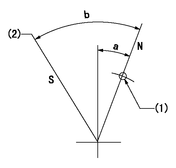
N:Pump normal
S:Stop the pump.
(1)Use the pin at R = aa
(2)Set the stopper bolt so that speed = bb and rack position = cc. (Confirm non-injection.)
----------
aa=40mm bb=0r/min cc=1.5+-0.3mm
----------
a=20deg+-5deg b=43deg+-5deg
----------
aa=40mm bb=0r/min cc=1.5+-0.3mm
----------
a=20deg+-5deg b=43deg+-5deg
0000001501 ACS
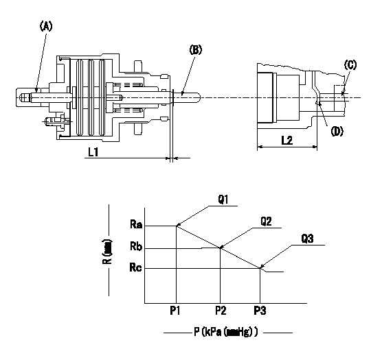
(A) Set screw
(B) Push rod 1
(C) Push rod 2
(D) Lever
1. Aneroid compensator unit adjustment
(1)Screw in (A) to obtain L1.
(2)Select C so that dimension L2 can be obtained.
2. Adjustment when mounting the governor.
(1)Set the speed of the pump to N1 r/min and fix the control lever at the full set position.
(2)Set to full boost.
(3)Screw in the aneroid compensator body to obtain the performance shown in the graph above.
(4)As there is hysterisis, measure when the absolute pressure drops.
(5)Hysterisis must not exceed rack position = h1.
----------
N1=1150r/min L1=1.5+-0.5mm L2=36+-0.5mm h1=0.15mm
----------
Ra=R3(R1+1.5)mm Rb=- Rc=R3-0.8mm P1=(89.8)+-2.7kPa((674)+-20mmHg) P2=- P3=65.2+-0.7kPa(489+-5mmHg) Q1=(133)+-2cm3/1000st Q2=- Q3=(119)cm3/1000st
----------
N1=1150r/min L1=1.5+-0.5mm L2=36+-0.5mm h1=0.15mm
----------
Ra=R3(R1+1.5)mm Rb=- Rc=R3-0.8mm P1=(89.8)+-2.7kPa((674)+-20mmHg) P2=- P3=65.2+-0.7kPa(489+-5mmHg) Q1=(133)+-2cm3/1000st Q2=- Q3=(119)cm3/1000st
0000001601 TAMPER PROOF
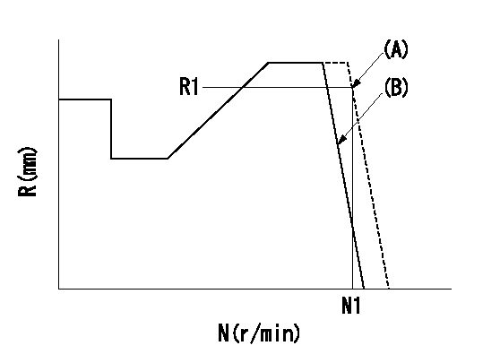
(A): Rotation tamper proof
(B): Full-speed setting
1. Back off the full-speed set bolt.
2. Confirm that the tamper setting position is N1, R1, Q1.
3. At that time, record the angle of the speed lever.
4. After confirming the above setting, set full speed.
----------
N1=(1490)r/min R1=6.8+-0.1mm Q1=-
----------
----------
N1=(1490)r/min R1=6.8+-0.1mm Q1=-
----------
Timing setting

(1)Pump vertical direction
(2)Position of "Z" mark at the No 1 cylinder's beginning of injection (governor side)
(3)B.T.D.C.: aa
(4)-
----------
aa=10deg
----------
a=(170deg)
----------
aa=10deg
----------
a=(170deg)
Information:
B. Back out (loosen) the lift adjustment screw 3/4 1/8of a turn.C. Put the nozzle in a vise with 8S2250 Holding Tool (1). Hold pressure adjusting screw (4) and tighten the locknut to a torque of 8.0-8.5 N m (70-75 lb in) using the 2P5487 Adapter (A). Recheck the opening pressure.Adjustment of 9L7883 Nozzles
1. Remove the nozzle from the tester and place in a vise using 8S2250 Nozzle Holding Tool (1). Loosen lift adjusting screw locknut (2). Loosen lift adjusting screw (3) two full turns counterclockwise.
If lift adjusting screw (3) is not loosened, the valve can be damaged in later steps.
2. Loosen pressure adjusting screw (4) and remove the nozzle from the nozzle holding tool. 3. Tilt the nozzle slightly down from the vertical position and remove pressure screw (4) and shims (5). If the shims do not come out of the nozzle, invert the nozzle and let the shims, spring and spring seat fall into the hand. If the valve comes out of its own weight, handle it carefully by its stem.4. To increase the opening pressure, add a 4N5730 Shim. The 4N5730 Shim is 0.13 mm (.005") thick and will increase the opening pressure approximately 1725 kPa (250 psi). A maximum of two shims can be added; if two shims do not increase opening pressure to specification given, discard the nozzle. 5. Assemble the nozzle, making sure the thickest shim (C) is against pressure screw (4). Put the nozzle in a vise using 8S2250 Nozzle Holding Tool (1). Tighten the pressure adjusting screw to 8.0-9.1 N m (70-80 lb in) torque.6. Remove the nozzle from the holding tool. Connect the nozzle, with the tip facing downward, to the tester. Point the nozzle tip into the 8S2270 Fuel Collector and the FT1384 Extension. Check the opening pressure and if it is not within specifications, repeat steps 4 and 5.Valve Lift Adjustment-9L7883 Nozzles
A. When the correct opening pressure is set, and while pumping test fluid through the nozzle, hold the lift adjusting screw locknut and slowly turn the lift adjusting screw clockwise (CW) until valve pressure rises 1380-3450 kPa (200-500 psi) above the nozzle opening pressure. Some test fluid may collect on the tip, but it must not flow at a rapid dribble.
Do not bend the valve by bottoming with too much force.
B. Back out the lift screw 3/4 1/8 turn, hold the lift adjusting screw, and tighten the locknut just enough so the screw will not turn; the lift is now set. C. Put the nozzle in a vise using 8S2250 Holding Tool (1). Tighten the locknut to 4.0-4.5 N m (35-40 lb in). Recheck valve opening pressure.Adjustment of 9L6969, 7N0449, 9N3299, 9N3700, 9N3979, 1W5829, 4W1819, 4W8483 and 7W3710 Nozzles
1. Put the nozzle in a vise using the 8S2250 Holding Tool (1). Loosen lift adjusting screw locknut (2). Turn lift adjusting screw (3) two full turns counterclockwise (CCW). 2. Hold lift adjusting screw (3) with a .08 mm (5/64") hex wrench (4) and