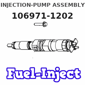
Information injection-pump assembly
ZEXEL
106971-1202
1069711202
ISUZU
1156031862
1156031862
Rating:
Cross reference number
ZEXEL
106971-1202
1069711202
ISUZU
1156031862
1156031862
Zexel num
Bosch num
Firm num
Name
Calibration Data:
Adjustment conditions
Test oil
1404 Test oil ISO4113 or {SAEJ967d}
1404 Test oil ISO4113 or {SAEJ967d}
Test oil temperature
degC
40
40
45
Nozzle and nozzle holder
105780-8250
Bosch type code
1 688 901 101
Nozzle
105780-0120
Bosch type code
1 688 901 990
Nozzle holder
105780-2190
Opening pressure
MPa
20.7
Opening pressure
kgf/cm2
211
Injection pipe
Outer diameter - inner diameter - length (mm) mm 8-3-600
Outer diameter - inner diameter - length (mm) mm 8-3-600
Overflow valve
134424-4320
Overflow valve opening pressure
kPa
255
221
289
Overflow valve opening pressure
kgf/cm2
2.6
2.25
2.95
Tester oil delivery pressure
kPa
255
255
255
Tester oil delivery pressure
kgf/cm2
2.6
2.6
2.6
RED3 control unit part number
407910-3
960
RED3 rack sensor specifications
mm
19
Direction of rotation (viewed from drive side)
Right R
Right R
Injection timing adjustment
Direction of rotation (viewed from drive side)
Right R
Right R
Injection order
1-8-7-6-
5-4-3-10
-9-2
Pre-stroke
mm
5.5
5.47
5.53
Rack position
Point A R=A
Point A R=A
Beginning of injection position
Governor side NO.1
Governor side NO.1
Difference between angles 1
Cal 1-8 deg. 27 26.75 27.25
Cal 1-8 deg. 27 26.75 27.25
Difference between angles 2
Cal 1-7 deg. 72 71.75 72.25
Cal 1-7 deg. 72 71.75 72.25
Difference between angles 3
Cal 1-6 deg. 99 98.75 99.25
Cal 1-6 deg. 99 98.75 99.25
Difference between angles 4
Cal 1-5 deg. 144 143.75 144.25
Cal 1-5 deg. 144 143.75 144.25
Difference between angles 5
Cal 1-4 deg. 171 170.75 171.25
Cal 1-4 deg. 171 170.75 171.25
Difference between angles 6
Cal 1-3 deg. 216 215.75 216.25
Cal 1-3 deg. 216 215.75 216.25
Difference between angles 7
Cal 1-10 deg. 243 242.75 243.25
Cal 1-10 deg. 243 242.75 243.25
Difference between angles 8
Cal 1-9 deg. 288 287.75 288.25
Cal 1-9 deg. 288 287.75 288.25
Difference between angles 9
Cyl.1-2 deg. 315 314.75 315.25
Cyl.1-2 deg. 315 314.75 315.25
Injection quantity adjustment
Rack position
(11.4)
Vist
V
2.14
2.14
2.14
Pump speed
r/min
700
700
700
Average injection quantity
mm3/st.
146.5
145.5
147.5
Max. variation between cylinders
%
0
-3
3
Basic
*
Remarks
Point A
Point A
Injection quantity adjustment_02
Rack position
(6.1)
Vist
V
2.9
2.8
3
Pump speed
r/min
490
490
490
Average injection quantity
mm3/st.
13.5
11.5
15.5
Max. variation between cylinders
%
0
-13
13
Test data Ex:
Governor adjustment

(1)Adjusting range
(2)Step response time
(N): Speed of the pump
(L): Load
(theta) Advance angle
(Srd1) Step response time 1
(Srd2) Step response time 2
1. Adjusting conditions for the variable timer
(1)Adjust the clearance between the pickup and the protrusion to L.
----------
L=1-0.2mm N2=800r/min C2=(8)deg t1=1.5--sec. t2=1.5--sec.
----------
N1=950++r/min P1=0kPa(0kgf/cm2) P2=392kPa(4kgf/cm2) C1=8+-0.3deg R01=0/4load R02=4/4load
----------
L=1-0.2mm N2=800r/min C2=(8)deg t1=1.5--sec. t2=1.5--sec.
----------
N1=950++r/min P1=0kPa(0kgf/cm2) P2=392kPa(4kgf/cm2) C1=8+-0.3deg R01=0/4load R02=4/4load
Speed control lever angle

N:Pump normal
S:Stop the pump.
(1)Rack position = aa
(2)Rack position bb
----------
aa=20mm bb=1mm
----------
a=37deg+-5deg b=37deg+-5deg
----------
aa=20mm bb=1mm
----------
a=37deg+-5deg b=37deg+-5deg
0000000901

(1)Pump vertical direction
(2)Position of "Z" mark at the No 1 cylinder's beginning of injection (governor side)
(3)B.T.D.C.: aa
(4)-
----------
aa=4deg
----------
a=(180deg)
----------
aa=4deg
----------
a=(180deg)
Stop lever angle

(Rs) rack sensor specifications
(C/U) control unit part number
(V) Rack sensor output voltage
(R) Rack position (mm)
1. Confirming governor output characteristics (rack 19 mm, span 6 mm)
(1)When the output voltages of the rack sensor are V1 and V2, check that the rack positions R1 and R2 in the table above are satisfied.
----------
----------
----------
----------
Information:
PARTS NEEDED
Qty
Part Number Description
6 10R7225 INJECTOR GP-FUEL
In order to allow equitable parts availability to all participating dealers, please limit your initial parts order to not exceed 18% of dealership population. This is an initial order recommendation only, and the ultimate responsibility for ordering the total number of parts needed to satisfy the program lies with the dealer.
ACTION REQUIRED
Take the following actions before or after a failure occurs on one or more injectors in any of the engines listed in this service letter.
- If one or more injectors fail it may be necessary to replace up to 6 injectors at the time of repair.
There will be situations when all 6 injectors do not have to be replaced. Refer to next paragraph to determine which injectors should be replaced.
- If an injector repair has previously been performed after approximately 01Oct07 on any of the listed engines, only the injectors that were not replaced at that time should be replaced. This should further be verified by comparing the injector serial numbers in the engine to a range of 3B115776403B to 3B11676551F9. Disregard the first and last two characters in the serial number (in this case "3B" and "3B" in the first serial number and "3B" and "F9" in the second serial number). The reason for verifying the serial number range is due to a batch change of the internal part that is failing. The change was made after serial number 3B11676551F9.
Only injectors falling within the range of 11577640-11676551 should be replaced.
- If the suspect injector can not be identified by using the automatic cylinder cutout test use the two methods below.
- First, run a manual cylinder cutout test at a high engine speed with some load on the engine. When the injector that has failed is cutout, the sound of the engine should be more normal as opposed to the loud knocking heard when the failed injector is active. The second method is to unplug the wiring harness at the valve cover base that sends current to the injector solenoids as well as the harness connection for the injection actuation pressure sensor. By making these disconnections, the fuel injectors will not fire and the HEUI pump will go to maximum actuation pressure. Then remove the valve cover and crank the engine. The injectors that have failed should expel more oil (from the HEUI System) than those that are not failed.
-Refer to RENR9579 for removal/install procedure of the unit injector.
-The serial number of all injectors replaced in an engine covered under this service letter must be documented in the claims story.
SERVICE CLAIM ALLOWANCES
Product smu/age whichever comes first Caterpillar Dealer Suggested Customer Suggested
Parts % Labor Hrs% Parts % Labor Hrs% Parts % Labor Hrs%
0-1000 hrs,
0-24 mo 100.0% 100.0% 0.0% 0.0% 0.0% 0.0%
This is a 4.0-hour job
The serial number of any injector(s) replaced in a machine covered under this service letter must be documented in the claims story. Only injectors with serial numbers between 11577640-11676551 (see action required for explanation on how to decode injector serial number) will be