Information injection-pump assembly
ZEXEL
106971-0930
1069710930
Rating:
Service parts 106971-0930 INJECTION-PUMP ASSEMBLY:
1.
_
7.
COUPLING PLATE
8.
_
9.
_
11.
Nozzle and Holder
16600-97071
12.
Open Pre:MPa(Kqf/cm2)
17.7{180}/21.6{220}
15.
NOZZLE SET
Include in #1:
106971-0930
as INJECTION-PUMP ASSEMBLY
Cross reference number
ZEXEL
106971-0930
1069710930
Zexel num
Bosch num
Firm num
Name
106971-0930
INJECTION-PUMP ASSEMBLY
Calibration Data:
Adjustment conditions
Test oil
1404 Test oil ISO4113 or {SAEJ967d}
1404 Test oil ISO4113 or {SAEJ967d}
Test oil temperature
degC
40
40
45
Nozzle and nozzle holder
105780-8140
Bosch type code
EF8511/9A
Nozzle
105780-0000
Bosch type code
DN12SD12T
Nozzle holder
105780-2080
Bosch type code
EF8511/9
Opening pressure
MPa
17.2
Opening pressure
kgf/cm2
175
Injection pipe
Outer diameter - inner diameter - length (mm) mm 8-3-600
Outer diameter - inner diameter - length (mm) mm 8-3-600
Overflow valve
132424-0620
Overflow valve opening pressure
kPa
157
123
191
Overflow valve opening pressure
kgf/cm2
1.6
1.25
1.95
Tester oil delivery pressure
kPa
157
157
157
Tester oil delivery pressure
kgf/cm2
1.6
1.6
1.6
Direction of rotation (viewed from drive side)
Right R
Right R
Injection timing adjustment
Direction of rotation (viewed from drive side)
Right R
Right R
Injection order
10-9-4-3
-6-5-8-7
-2-1
Pre-stroke
mm
3.65
3.6
3.7
Beginning of injection position
Governor side NO.1
Governor side NO.1
Difference between angles 1
Cal 10-9 deg. 45 44.5 45.5
Cal 10-9 deg. 45 44.5 45.5
Difference between angles 2
Cal 10-4 deg. 72 71.5 72.5
Cal 10-4 deg. 72 71.5 72.5
Difference between angles 3
Cal 10-3 deg. 117 116.5 117.5
Cal 10-3 deg. 117 116.5 117.5
Difference between angles 4
Cal 10-6 deg. 144 143.5 144.5
Cal 10-6 deg. 144 143.5 144.5
Difference between angles 5
Cal 10-5 deg. 189 188.5 189.5
Cal 10-5 deg. 189 188.5 189.5
Difference between angles 6
Cal 10-8 deg. 216 215.5 216.5
Cal 10-8 deg. 216 215.5 216.5
Difference between angles 7
Cal 10-7 deg. 261 260.5 261.5
Cal 10-7 deg. 261 260.5 261.5
Difference between angles 8
Cal 10-2 deg. 288 287.5 288.5
Cal 10-2 deg. 288 287.5 288.5
Difference between angles 9
Cal 10-1 deg. 333 332.5 333.5
Cal 10-1 deg. 333 332.5 333.5
Injection quantity adjustment
Adjusting point
A
Rack position
9.8
Pump speed
r/min
700
700
700
Average injection quantity
mm3/st.
121
120
122
Max. variation between cylinders
%
0
-4
4
Basic
*
Fixing the lever
*
Injection quantity adjustment_02
Adjusting point
B
Rack position
9.45
Pump speed
r/min
1100
1100
1100
Average injection quantity
mm3/st.
117.5
115.5
119.5
Max. variation between cylinders
%
0
-4
4
Fixing the lever
*
Injection quantity adjustment_03
Adjusting point
C
Rack position
6.4+-0.5
Pump speed
r/min
235
235
235
Average injection quantity
mm3/st.
10.4
8.4
12.4
Max. variation between cylinders
%
0
-10
10
Fixing the rack
*
Injection quantity adjustment_04
Adjusting point
E
Rack position
-
Pump speed
r/min
100
100
100
Average injection quantity
mm3/st.
120
120
Fixing the lever
*
Remarks
After startup boost setting
After startup boost setting
Timer adjustment
Pump speed
r/min
1000
Advance angle
deg.
2
1.5
2.5
Timer adjustment_02
Pump speed
r/min
1100
Advance angle
deg.
5
4.5
5.5
Remarks
Finish
Finish
Test data Ex:
Governor adjustment
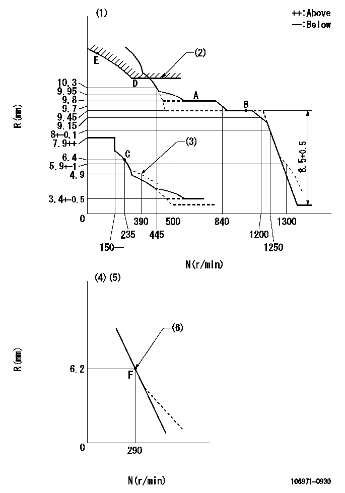
N:Pump speed
R:Rack position (mm)
(1)Tolerance for racks not indicated: +-0.05mm.
(2)Excess fuel setting for starting: SXL (N = N1)
(3)Damper spring setting
(4)Variable speed specification: idling adjustment
(5)Fix the lever at the full-load position at delivery.
(6)Main spring setting
----------
SXL=10.4+-0.1mm N1=400r/min
----------
----------
SXL=10.4+-0.1mm N1=400r/min
----------
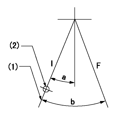
Speed control lever angle

F:Full speed
I:Idle
(1)Pump speed = aa
(2)Set the stopper bolt (fixed at full-load position at delivery.)
----------
aa=290r/min
----------
a=15deg+-5deg b=6deg+-5deg
----------
aa=290r/min
----------
a=15deg+-5deg b=6deg+-5deg
0000000901
F:Full load
I:Idle
(1)Stopper bolt setting
(2)Use the hole at R = aa
----------
aa=64.3mm
----------
a=18.5deg+-5deg b=24deg+-3deg
----------
aa=64.3mm
----------
a=18.5deg+-5deg b=24deg+-3deg
Stop lever angle
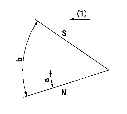
N:Pump normal
S:Stop the pump.
(1)Drive side
----------
----------
a=12deg+-5deg b=64deg+-5deg
----------
----------
a=12deg+-5deg b=64deg+-5deg
Timing setting
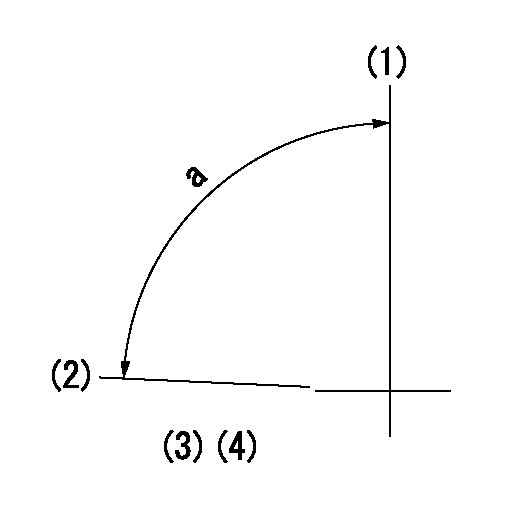
(1)Pump vertical direction
(2)Position of the coupling's key groove at the start of injection for the No. 10 cylinder.
(3)-
(4)-
----------
----------
a=(90deg)
----------
----------
a=(90deg)
Information:
This Program must be administered as soon as possible. When reporting the repair, use "PI3330" as the Part Number, "7751" as the Group Number, "56" as the Warranty Claim Description Code and "T" as the SIMS Description Code. Exception: If the repair is done after failure, use "PI3330" as the Part Number, "7751" as the Group Number, "96" as the Warranty Claim Description Code, and "Z" as the SIMS Description Code.
Completion Date
March 31, 2000Termination Date
September 30, 2000Problem
The torque of the injector electronic solenoid valves need to be checked. The valve has four Torx bolts that hold the stator to the housing. If these bolts are not properly tightened, fuel can leak into the oil.
Affected Product
Model & Identification Number
D11R (9TR441-442)
776D (5ER126, 5ER127)
785C (1HW122)
793C (4GZ165-167)
777D (3PR1058, 3PR1057, 3PR1061, 3PR1059, 3PR1060, 3PR1063)
3508B (3DM157-159 4GM426-439 6PN532-533 , 6PN535-536, 6PN539-540, 6PN542-543 5PS225-234 2HW125-126 1FZ366-370 )
3512 (6PM38-39 3MS186 3RS329 )
3512B (8EM317-318 8RM395-397 4TM215-217 3ZW131-134 6WN349-356 )
3516 (7KM50-51 3SS306-307 )
3516B (6HN384, 6HN390, 6HN392, 6HN394, 6HN398 7RN818-819 , 7RN821, 7RN824, 7RN826-827, 7RN833, 7RN836-840, 7RN850, 7RN852 8KN368-369 , 8KN372, 8KN373 7TR818 4BW333-334 )
Parts Needed
Dealers will not need to order parts for this Program.
Action Required
See the attached procedure.
Owner Notification
U.S. and Canadian owners will receive the attached Owner Notification.
Service Claim Allowances
This is a 3-hour job.
U.S. and Canadian Dealers Only - Eligible dealers may enter a Type 2 SIMS Report.
Parts Disposition
Handle the parts in accordance with your Warranty Bulletin on warranty parts handling.
MAKE EVERY EFFORT TO COMPLETE THIS PROGRAM AS SOON AS POSSIBLE.
Attach.(1-Owner Notification)(Torque Procedure)Copy Of Owner Notification For U.S. And Canadian Owners
Torque Procedure For Electronic 3500B Injector Bolts
THIS REWORK IS RESTRICTED TO ENGINES LISTED IN THE AFFECTED PRODUCT ONLY.
THIS PIP DOES NOT ALLOW FOR THE REMOVAL OF THE INJECTOR. DO NOT REMOVE ANY OF THE STATOR BOLTS. THIS WILL VOID INJECTOR WARRANTY.
PROCEDURE:
1. Remove the valve covers to reveal the injector assembly/ electronic valve.2. Remove electronic valve terminal connector (two retaining nuts) with a " universal socket. Take the terminal connectors off of the posts.3. The four stator retaining bolts you need to check are now accessible. To properly complete the torque check, the following tools are required.a) Click torque wrench, " drive (capable of accurately measuring 2.0 N m)b) 6" extension " drive.c) universal joint, "drived) T10 Torx bit, " drive4. Set the torque wrench value to (2.1 N m). Check all four bolts and tighten (if needed) until they reach the 2.1 specification.:
DO NOT OVER TORQUE THE STATOR RETAINING BOLTS (2.1 N m). THIS COULD CAUSE FURTHER DAMAGE.
5. Reassemble the engine in the reverse order.a) Torque value of the terminal connector nuts - 3.0 N m b) Torque value for the valve cover bolts - 47 9 N m.
Have questions with 106971-0930?
Group cross 106971-0930 ZEXEL
Nissan-Diesel
Nissan-Diesel
106971-0930
INJECTION-PUMP ASSEMBLY
