Information injection-pump assembly
ZEXEL
106971-0870
1069710870

Rating:
Service parts 106971-0870 INJECTION-PUMP ASSEMBLY:
1.
_
7.
COUPLING PLATE
8.
_
9.
_
11.
Nozzle and Holder
16600-97073
12.
Open Pre:MPa(Kqf/cm2)
17.7{180}/21.6{220}

15.
NOZZLE SET
Include in #1:
106971-0870
as INJECTION-PUMP ASSEMBLY
Cross reference number
ZEXEL
106971-0870
1069710870
Zexel num
Bosch num
Firm num
Name
106971-0870
INJECTION-PUMP ASSEMBLY
Calibration Data:
Adjustment conditions
Test oil
1404 Test oil ISO4113 or {SAEJ967d}
1404 Test oil ISO4113 or {SAEJ967d}
Test oil temperature
degC
40
40
45
Nozzle and nozzle holder
105780-8140
Bosch type code
EF8511/9A
Nozzle
105780-0000
Bosch type code
DN12SD12T
Nozzle holder
105780-2080
Bosch type code
EF8511/9
Opening pressure
MPa
17.2
Opening pressure
kgf/cm2
175
Injection pipe
Outer diameter - inner diameter - length (mm) mm 8-3-600
Outer diameter - inner diameter - length (mm) mm 8-3-600
Overflow valve
132424-0620
Overflow valve opening pressure
kPa
157
123
191
Overflow valve opening pressure
kgf/cm2
1.6
1.25
1.95
Tester oil delivery pressure
kPa
157
157
157
Tester oil delivery pressure
kgf/cm2
1.6
1.6
1.6
Direction of rotation (viewed from drive side)
Right R
Right R
Injection timing adjustment
Direction of rotation (viewed from drive side)
Right R
Right R
Injection order
10-9-4-3
-6-5-8-7
-2-1
Pre-stroke
mm
3.65
3.6
3.7
Beginning of injection position
Governor side NO.1
Governor side NO.1
Difference between angles 1
Cal 10-9 deg. 45 44.5 45.5
Cal 10-9 deg. 45 44.5 45.5
Difference between angles 2
Cal 10-4 deg. 72 71.5 72.5
Cal 10-4 deg. 72 71.5 72.5
Difference between angles 3
Cal 10-3 deg. 117 116.5 117.5
Cal 10-3 deg. 117 116.5 117.5
Difference between angles 4
Cal 10-6 deg. 144 143.5 144.5
Cal 10-6 deg. 144 143.5 144.5
Difference between angles 5
Cal 10-5 deg. 189 188.5 189.5
Cal 10-5 deg. 189 188.5 189.5
Difference between angles 6
Cal 10-8 deg. 216 215.5 216.5
Cal 10-8 deg. 216 215.5 216.5
Difference between angles 7
Cal 10-7 deg. 261 260.5 261.5
Cal 10-7 deg. 261 260.5 261.5
Difference between angles 8
Cal 10-2 deg. 288 287.5 288.5
Cal 10-2 deg. 288 287.5 288.5
Difference between angles 9
Cal 10-1 deg. 333 332.5 333.5
Cal 10-1 deg. 333 332.5 333.5
Injection quantity adjustment
Adjusting point
A
Rack position
9.6
Pump speed
r/min
700
700
700
Average injection quantity
mm3/st.
118.4
117.4
119.4
Max. variation between cylinders
%
0
-4
4
Basic
*
Fixing the lever
*
Injection quantity adjustment_02
Adjusting point
B
Rack position
9.4+-0.5
Pump speed
r/min
1100
1100
1100
Average injection quantity
mm3/st.
118.1
116.1
120.1
Max. variation between cylinders
%
0
-4
4
Fixing the lever
*
Injection quantity adjustment_03
Adjusting point
C
Rack position
6.7+-0.5
Pump speed
r/min
235
235
235
Average injection quantity
mm3/st.
10.4
8.4
12.4
Max. variation between cylinders
%
0
-10
10
Fixing the rack
*
Injection quantity adjustment_04
Adjusting point
D
Rack position
11.7+-0.
1
Pump speed
r/min
100
100
100
Average injection quantity
mm3/st.
135
135
155
Fixing the lever
*
Rack limit
*
Timer adjustment
Pump speed
r/min
1000
Advance angle
deg.
1.1
0.6
1.6
Timer adjustment_02
Pump speed
r/min
1100
Advance angle
deg.
5
4.5
5.5
Remarks
Finish
Finish
Test data Ex:
Governor adjustment

N:Pump speed
R:Rack position (mm)
(1)Tolerance for racks not indicated: +-0.05mm.
(2)Rack limit using the stop lever: R1
(3)Excess fuel setting for starting: SXL (N = N1)
(4)Damper spring setting
(5)Variable speed specification: idling adjustment
(6)Fix the lever at the full-load position at delivery.
(7)Main spring setting
----------
R1=11.7+-0.1mm SXL=10.3+-0.1mm N1=410r/min
----------
----------
R1=11.7+-0.1mm SXL=10.3+-0.1mm N1=410r/min
----------
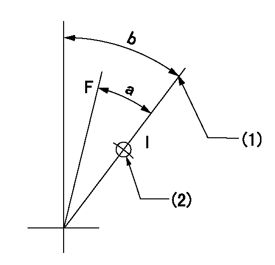
Speed control lever angle

F:Full speed
I:Idle
(1)Pump speed = aa
(2)Set the stopper bolt (fixed at full-load position at delivery.)
----------
aa=290r/min
----------
a=(13deg)+-5deg b=7deg+-5deg
----------
aa=290r/min
----------
a=(13deg)+-5deg b=7deg+-5deg
0000000901
F:Full load
I:Idle
(1)Use the hole at R = aa
(2)Stopper bolt setting
----------
aa=46mm
----------
a=24deg+-3deg b=33deg+-5deg
----------
aa=46mm
----------
a=24deg+-3deg b=33deg+-5deg
Stop lever angle

N:Pump normal
S:Stop the pump.
(1)Drive side
(2)Rack position = aa
----------
aa=11.7+-0.1mm
----------
a=28deg+-5deg b=30deg+-5deg
----------
aa=11.7+-0.1mm
----------
a=28deg+-5deg b=30deg+-5deg
Timing setting

(1)Pump vertical direction
(2)Position of the coupling's key groove at the start of injection for the No. 10 cylinder.
(3)-
(4)-
----------
----------
a=(90deg)
----------
----------
a=(90deg)
Information:
Caterpillar: Confidential Yellow
OPTIONAL:IMPROVED FUEL TRANSFER PUMP SEALS FOR COLD WEATHER OPERATION; CHECK FOR NOZZLE GAS LEAKAGE - 3406B IN ALL APP LICATIONS - PI7090 - MAILED US AND CANADA, CACO, COFA, BRAZIL, CFEL, COSA, TRUCK, MARINE & AGRICULTURE TEPS
The information supplied in this service letter may not be valid after the termination date of this program. Do not perform the work outlined in this Service Letter after the termination date without first contacting your Caterpillar product analyst.
IMPROVED FUEL TRANSFER PUMP VALVES FOR COLD WEATHER OPERATION; CHECK FOR NOZZLE GAS LEAKAGE, 3406B Truck, Marine, And Industrial Engines; 3406B Generator Sets; 16G Motor Graders; 245 Excavators And Front Shovels; 824C Tractors; 825C, 826C Compactors; 980C Loaders, 1254, 1256, 1250, PI7090 U-56 A-36 AU-47 B-21 C-51 E-34 O-42 TT-3 TA-3 TM-4 optional parts stock action needed If you received the January 6, 1984 Safety Service Letter (PI1019) and/or the December 2, 1983 Service Letter (PI7049), do all three PIP's at the same time. Problems ****Transfer Pump Valves**** The fuel transfer pump on the above engines has three 1W6182 Valve Assemblies. The one valve in the piston can break in extremely cold weather due to excessive restriction from jelled fuel. Some damage can also occur to the other valve assemblies. A new valve with less flow restriction is now used in the piston and at the other two locations in the pump. These valves are directly adaptable to earlier engines. ****Combustion Gas Leakage Around Fuel Nozzles**** There is a possibility that combustion gases can escape by a fuel injection nozzle and into the adapter. The high temperatures soften the end of the nozzle body and cause the tip to come off. The usual cause for escaping combustion gases is either a loose nozzle in the adapter or a cut in the carbon dam (gas seal). See Illustration 1. Nozzle hold down clamps are all now tightened properly, and an improved chamfer is machined inside the bottom of the adapters to prevent cutting the carbon dam. ILLUSTRATION 1 (SEE ILLUSTRATION) Affected Models And Parts Needed Some of the following vehicles contain the 3406 Engine with the former scroll fuel system and are not in this Program. PIN's (Product Identification No.) Or Serial No. Model Both Problems Gas Leakage Only 3406B Truck Engine 7FB1-8348 8349 - 10145 3406B Marine Engine 4TB1-383 384 - 396 3406B Industrial Engine 6TB1-1184 1185 - 1276 3406B Generator Set 2WB1-1044 1045 - 1166 16G Motor Grader 93U2284-93U2417 93U2418-93U2432 245 Excavator 95V1084-95V1111 95V1112-95V1116 245 Excavator
Have questions with 106971-0870?
Group cross 106971-0870 ZEXEL
Nissan-Diesel
Nissan-Diesel
Nissan-Diesel
Nissan-Diesel
Nissan-Diesel
Nissan-Diesel
Nissan-Diesel
Nissan-Diesel
106971-0870
INJECTION-PUMP ASSEMBLY