Information injection-pump assembly
ZEXEL
106971-0860
1069710860
Rating:
Service parts 106971-0860 INJECTION-PUMP ASSEMBLY:
1.
_
7.
COUPLING PLATE
8.
_
9.
_
11.
Nozzle and Holder
16600-97071
12.
Open Pre:MPa(Kqf/cm2)
17.7{180}/21.6{220}
15.
NOZZLE SET
Include in #1:
106971-0860
as INJECTION-PUMP ASSEMBLY
Cross reference number
ZEXEL
106971-0860
1069710860
Zexel num
Bosch num
Firm num
Name
106971-0860
INJECTION-PUMP ASSEMBLY
Calibration Data:
Adjustment conditions
Test oil
1404 Test oil ISO4113 or {SAEJ967d}
1404 Test oil ISO4113 or {SAEJ967d}
Test oil temperature
degC
40
40
45
Nozzle and nozzle holder
105780-8140
Bosch type code
EF8511/9A
Nozzle
105780-0000
Bosch type code
DN12SD12T
Nozzle holder
105780-2080
Bosch type code
EF8511/9
Opening pressure
MPa
17.2
Opening pressure
kgf/cm2
175
Injection pipe
Outer diameter - inner diameter - length (mm) mm 8-3-600
Outer diameter - inner diameter - length (mm) mm 8-3-600
Overflow valve opening pressure
kPa
157
123
191
Overflow valve opening pressure
kgf/cm2
1.6
1.25
1.95
Tester oil delivery pressure
kPa
157
157
157
Tester oil delivery pressure
kgf/cm2
1.6
1.6
1.6
Direction of rotation (viewed from drive side)
Right R
Right R
Injection timing adjustment
Direction of rotation (viewed from drive side)
Right R
Right R
Injection order
10-9-4-3
-6-5-8-7
-2-1
Pre-stroke
mm
3.65
3.6
3.7
Beginning of injection position
Governor side NO.1
Governor side NO.1
Difference between angles 1
Cal 10-9 deg. 45 44.5 45.5
Cal 10-9 deg. 45 44.5 45.5
Difference between angles 2
Cal 10-4 deg. 72 71.5 72.5
Cal 10-4 deg. 72 71.5 72.5
Difference between angles 3
Cal 10-3 deg. 117 116.5 117.5
Cal 10-3 deg. 117 116.5 117.5
Difference between angles 4
Cal 10-6 deg. 144 143.5 144.5
Cal 10-6 deg. 144 143.5 144.5
Difference between angles 5
Cal 10-5 deg. 189 188.5 189.5
Cal 10-5 deg. 189 188.5 189.5
Difference between angles 6
Cal 10-8 deg. 216 215.5 216.5
Cal 10-8 deg. 216 215.5 216.5
Difference between angles 7
Cal 10-7 deg. 261 260.5 261.5
Cal 10-7 deg. 261 260.5 261.5
Difference between angles 8
Cal 10-2 deg. 288 287.5 288.5
Cal 10-2 deg. 288 287.5 288.5
Difference between angles 9
Cal 10-1 deg. 333 332.5 333.5
Cal 10-1 deg. 333 332.5 333.5
Injection quantity adjustment
Adjusting point
A
Rack position
9.8
Pump speed
r/min
700
700
700
Average injection quantity
mm3/st.
121
120
122
Max. variation between cylinders
%
0
-4
4
Basic
*
Fixing the lever
*
Injection quantity adjustment_02
Adjusting point
B
Rack position
9.45
Pump speed
r/min
1100
1100
1100
Average injection quantity
mm3/st.
117.5
115.5
119.5
Max. variation between cylinders
%
0
-4
4
Fixing the lever
*
Injection quantity adjustment_03
Adjusting point
C
Rack position
6.4+-0.5
Pump speed
r/min
235
235
235
Average injection quantity
mm3/st.
10.4
8.4
12.4
Max. variation between cylinders
%
0
-10
10
Fixing the rack
*
Injection quantity adjustment_04
Adjusting point
E
Rack position
-
Pump speed
r/min
100
100
100
Average injection quantity
mm3/st.
120
120
Fixing the lever
*
Remarks
After startup boost setting
After startup boost setting
Timer adjustment
Pump speed
r/min
1000
Advance angle
deg.
2
1.5
2.5
Timer adjustment_02
Pump speed
r/min
1100
Advance angle
deg.
5
4.5
5.5
Remarks
Finish
Finish
Test data Ex:
Governor adjustment
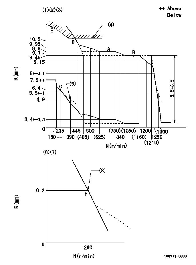
N:Pump speed
R:Rack position (mm)
(1)Lever ratio: RT
(2)Target shim dimension: TH
(3)Tolerance for racks not indicated: +-0.05mm.
(4)Excess fuel setting for starting: SXL
(5)Damper spring setting
(6)Variable speed specification: idling adjustment
(7)Fix the lever at the full-load position at delivery.
(8)Main spring setting
----------
RT=1 TH=2.4mm SXL=10.4+-0.1mm
----------
----------
RT=1 TH=2.4mm SXL=10.4+-0.1mm
----------
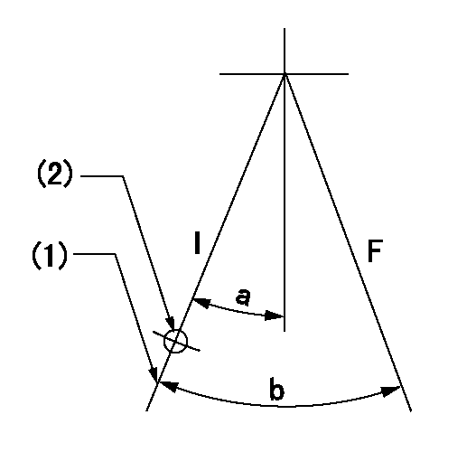
Speed control lever angle

F:Full speed
I:Idle
(1)(Pump speed = aa)
(2)Set the stopper bolt (fixed at full-load position at delivery.)
----------
aa=290r/min
----------
a=15deg+-5deg b=6deg+-5deg
----------
aa=290r/min
----------
a=15deg+-5deg b=6deg+-5deg
0000000901
F:Full load
I:Idle
(1)Stopper bolt setting
(2)Use the hole at R = aa
----------
aa=64.3mm
----------
a=18.5deg+-5deg b=24deg+-3deg
----------
aa=64.3mm
----------
a=18.5deg+-5deg b=24deg+-3deg
Stop lever angle
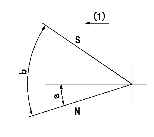
N:Pump normal
S:Stop the pump.
(1)Drive side
----------
----------
a=12deg+-5deg b=64deg+-5deg
----------
----------
a=12deg+-5deg b=64deg+-5deg
Timing setting
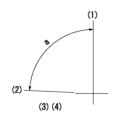
(1)Pump vertical direction
(2)Position of the coupling's key groove at the start of injection for the No. 10 cylinder.
(3)-
(4)-
----------
----------
a=(90deg)
----------
----------
a=(90deg)
Information:
(1) Distance from the end of the valve to the valve spring washer seat ... 2.063 .015 in.(52.40 0.38 mm)(2) Depth of bore in head for valve seat insert ... .442 .002 in.(11.23 0.05 mm)(3) Diameter of valve seat insert ... 1.9120 .0005 in.(48.565 0.013 mm) Bore in head for valve seat insert ... 1.9090 .0005 in.(44.489 0.013 mm)(4) Maximum permissible width of the face of the valve seat insert ... .105 in.(2.67 mm)(5) Angle of the face of the valve seat insert ... 451/4° 1/2°(6) Distance from head of valve to cylinder head face: Maximum permissible (valve closed) ... .085 in.(2.16 mm)Minimum permissible (valve closed) ... .050 in.(1.27 mm)(7) Outside diameter of the face of the valve seat insert ... 1.735 .005 in.(44.07 0.13 mm) Maximum permissible ... 1.760 in.(44.70 mm)(8) Angle to grind face of seat insert (to get a reduction of maximum seat diameter) ... 15°Intake Valve (without valve seat insert)
(1) Distance from the end of the valve to the valve spring washer seat ... 2.063 .015 in.(52.40 0.38 mm)(2) Maximum permissible width of the face of the valve seat ... 120 in.(3.05 mm)(3) Angle of the face of the valve seat ... 301/4° 1/2°(4) Distance from head of valve to cylinder head face: Maximum permissible (valve closed) ... .068 in.(1.73 mm)Minimum permissible (valve closed) ... .036 in.(0.91 mm)(5) Outside diameter of the valve seat ... 2.045 .005 in.(52.23 0.13 mm) Maximum permissible ... 2.065 in.(52.45 mm)(6) Diameter of the bore ... 2.150 in.(54.61 mm)(7) Maximum permissible depth of the bore to make the face of the valve seat smaller ... .170 in.(4.32 mm)Intake Valve (with valve seat insert)
TYPICAL ILLUSTRATION(1) Distance from the end of the valve to the valve spring washer seat ... 2.063 .015 in.(52.40 0.38 mm)(2) Depth of bore in head for valve seat insert ... .442 .002 in.(11.23 0.05 mm)(3) Diameter of valve seat insert ... 2.1500 .0005 in.(54.610 0.013 mm) Bore in head for valve seat insert ... 2.1470 .0005 in.(54.534 0.013 mm)(4) Maximum permissible width of the face of the valve seat insert ... .120 in.(3.05 mm)(5) Angle of the face of the valve seat insert ... 301/4° 1/2°(6) Distance from head of valve to cylinder head face: Maximum permissible (valve closed) ... .068 in.(1.73 mm)Minimum permissible (valve closed) ... .036 in.(0.91 mm)(7) Outside diameter of the face of the valve seat insert ... 2.045 .005 in.(52.23 0.13 mm) Maximum permissible ... 2.065 in.(52.45 mm)(8) Angle to grind face of seat insert (to get a reduction of maximum seat diameter) ... 15°
Have questions with 106971-0860?
Group cross 106971-0860 ZEXEL
Nissan-Diesel
Nissan-Diesel
Nissan-Diesel
Nissan-Diesel
Nissan-Diesel
Nissan-Diesel
Nissan-Diesel
106971-0860
INJECTION-PUMP ASSEMBLY
