Information injection-pump assembly
ZEXEL
106971-0800
1069710800
Rating:
Service parts 106971-0800 INJECTION-PUMP ASSEMBLY:
1.
_
7.
COUPLING PLATE
8.
_
9.
_
11.
Nozzle and Holder
16600-97073
12.
Open Pre:MPa(Kqf/cm2)
17.7{180}/21.6{220}
15.
NOZZLE SET
Include in #1:
106971-0800
as INJECTION-PUMP ASSEMBLY
Cross reference number
ZEXEL
106971-0800
1069710800
Zexel num
Bosch num
Firm num
Name
Calibration Data:
Adjustment conditions
Test oil
1404 Test oil ISO4113 or {SAEJ967d}
1404 Test oil ISO4113 or {SAEJ967d}
Test oil temperature
degC
40
40
45
Nozzle and nozzle holder
105780-8140
Bosch type code
EF8511/9A
Nozzle
105780-0000
Bosch type code
DN12SD12T
Nozzle holder
105780-2080
Bosch type code
EF8511/9
Opening pressure
MPa
17.2
Opening pressure
kgf/cm2
175
Injection pipe
Outer diameter - inner diameter - length (mm) mm 8-3-600
Outer diameter - inner diameter - length (mm) mm 8-3-600
Overflow valve opening pressure
kPa
157
123
191
Overflow valve opening pressure
kgf/cm2
1.6
1.25
1.95
Tester oil delivery pressure
kPa
157
157
157
Tester oil delivery pressure
kgf/cm2
1.6
1.6
1.6
Direction of rotation (viewed from drive side)
Right R
Right R
Injection timing adjustment
Direction of rotation (viewed from drive side)
Right R
Right R
Injection order
10-9-4-3
-6-5-8-7
-2-1
Pre-stroke
mm
3.65
3.6
3.7
Beginning of injection position
Governor side NO.1
Governor side NO.1
Difference between angles 1
Cal 10-9 deg. 45 44.5 45.5
Cal 10-9 deg. 45 44.5 45.5
Difference between angles 2
Cal 10-4 deg. 72 71.5 72.5
Cal 10-4 deg. 72 71.5 72.5
Difference between angles 3
Cal 10-3 deg. 117 116.5 117.5
Cal 10-3 deg. 117 116.5 117.5
Difference between angles 4
Cal 10-6 deg. 144 143.5 144.5
Cal 10-6 deg. 144 143.5 144.5
Difference between angles 5
Cal 10-5 deg. 189 188.5 189.5
Cal 10-5 deg. 189 188.5 189.5
Difference between angles 6
Cal 10-8 deg. 216 215.5 216.5
Cal 10-8 deg. 216 215.5 216.5
Difference between angles 7
Cal 10-7 deg. 261 260.5 261.5
Cal 10-7 deg. 261 260.5 261.5
Difference between angles 8
Cal 10-2 deg. 288 287.5 288.5
Cal 10-2 deg. 288 287.5 288.5
Difference between angles 9
Cal 10-1 deg. 333 332.5 333.5
Cal 10-1 deg. 333 332.5 333.5
Injection quantity adjustment
Adjusting point
A
Rack position
9.6
Pump speed
r/min
700
700
700
Average injection quantity
mm3/st.
118.4
117.4
119.4
Max. variation between cylinders
%
0
-4
4
Basic
*
Fixing the lever
*
Injection quantity adjustment_02
Adjusting point
B
Rack position
9.4+-0.5
Pump speed
r/min
1100
1100
1100
Average injection quantity
mm3/st.
118.1
116.1
120.1
Max. variation between cylinders
%
0
-4
4
Fixing the lever
*
Injection quantity adjustment_03
Adjusting point
C
Rack position
6.7+-0.5
Pump speed
r/min
235
235
235
Average injection quantity
mm3/st.
10.4
8.4
12.4
Max. variation between cylinders
%
0
-10
10
Fixing the rack
*
Injection quantity adjustment_04
Adjusting point
D
Rack position
-
Pump speed
r/min
100
100
100
Average injection quantity
mm3/st.
155
155
Fixing the lever
*
Remarks
After startup boost setting
After startup boost setting
Timer adjustment
Pump speed
r/min
1000
Advance angle
deg.
1.1
0.6
1.6
Timer adjustment_02
Pump speed
r/min
1100
Advance angle
deg.
5
4.5
5.5
Remarks
Finish
Finish
Test data Ex:
Governor adjustment
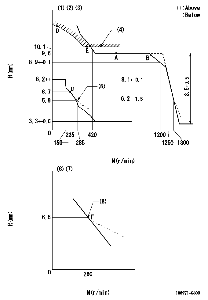
N:Pump speed
R:Rack position (mm)
(1)Lever ratio: RT
(2)Target shim dimension: TH
(3)Tolerance for racks not indicated: +-0.05mm.
(4)Excess fuel setting for starting: SXL
(5)Damper spring setting
(6)Variable speed specification: idling adjustment
(7)Fix the lever at the full-load position at delivery.
(8)Main spring setting
----------
RT=1 TH=2.2mm SXL=10.3+-0.1mm
----------
----------
RT=1 TH=2.2mm SXL=10.3+-0.1mm
----------
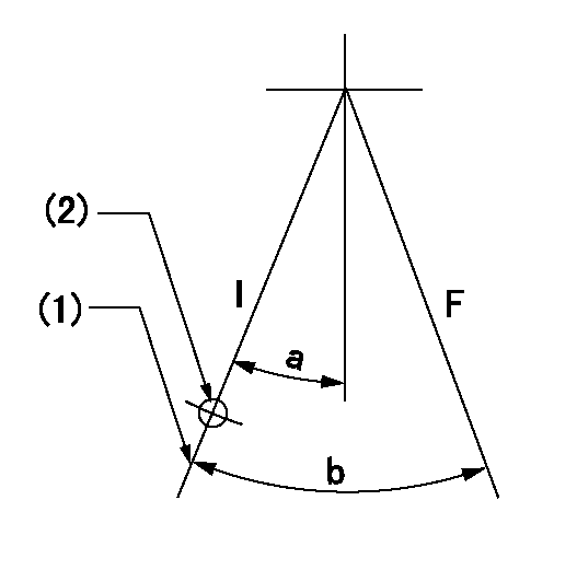
Speed control lever angle

F:Full speed
I:Idle
(1)(Pump speed = aa)
(2)Set the stopper bolt (fixed at full-load position at delivery.)
----------
aa=290r/min
----------
a=(13deg)+-5deg b=6deg+-5deg
----------
aa=290r/min
----------
a=(13deg)+-5deg b=6deg+-5deg
0000000901
F:Full load
I:Idle
(1)Stopper bolt setting
(2)Use the hole at R = aa
----------
aa=64.3mm
----------
a=18.5deg+-5deg b=23.5deg+-3deg
----------
aa=64.3mm
----------
a=18.5deg+-5deg b=23.5deg+-3deg
Stop lever angle
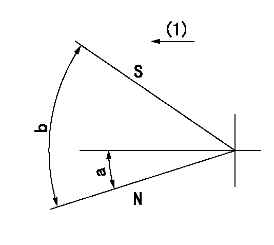
N:Pump normal
S:Stop the pump.
(1)Drive side
----------
----------
a=12deg+-5deg b=64deg+-5deg
----------
----------
a=12deg+-5deg b=64deg+-5deg
Timing setting
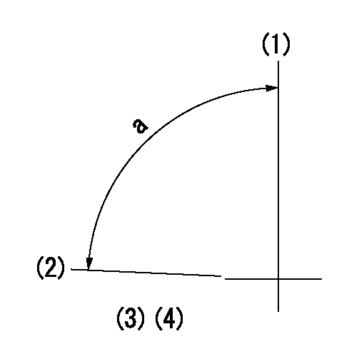
(1)Pump vertical direction
(2)Position of the coupling's key groove at the start of injection for the No. 10 cylinder.
(3)-
(4)-
----------
----------
a=(90deg)
----------
----------
a=(90deg)
Information:
Cautions Regarding Battery* Handle Battery Carefully * Never use flames or allow sparks near the battery. The battery releases flammable hydrogen gas and oxygen gas. These gases can be ignited by flames and cause an explosion.* Do not use the battery when the fluid surface is lower than the minimum level. Using a battery with a low electrolyte level can result in an explosion.* Do not short the battery terminals with a tool or other metal object.* When disconnecting battery cables, always remove the cable from the negative (-) terminal first. When reconnecting cables, attach the cable to the positive (+) terminal first.* Charge the battery in a well-ventilated area, with all filling hole plugs removed.* Make sure the cable clamps are securely installed on the battery terminals. A loose cable clamp can cause sparks that may result in an explosion.* Before servicing electrical components or conducting electrical welding, set the battery switch to the [Open/OFF] position or disconnect the cable from the negative (-) battery terminal to cut off the electrical current.* Electrolyte (battery fluid) contains dilute sulfuric acid. Careless handling of the battery can lead to the loss of sight and/or burns. Also, do not swallow electrolyte.* Wear protective goggles and rubber gloves when maintaining and inspecting the battery (when adding water, charging, etc.).* If electrolyte is spilled onto the skin or clothes, immediately wash with lots of clean fresh water and thoroughly clean with soap.* If electrolyte gets into eyes, immediately flush with lots of clean fresh water and seek immediate medical attention.* Should you accidentally swallow electrolyte, gargle with plenty of water, then drink lots of water, and seek immediate medical attention.
Response To Abnormalities* If Engine Overheats, Conduct Heating Operation Before Stopping The Engine If the engine overheats, do not stop the engine immediately. Abruptly stopping an overheated engine may cause the coolant temperature to rise, resulting in seizing of the engine. If the engine overheats, operate the engine at low idling speed (cooling operation), and stop the engine after the coolant temperature lowers sufficiently.Do not add coolant immediately after stopping the engine. Adding coolant to a hot engine may cause damage to the cylinder heads due to sudden change in temperature. Add coolant after the engine cools to room temperature.* If Engine Stops Due To Abnormality, Exercise Caution When Restarting If the engine stops due to an abnormality, do not restart the engine immediately. If the engine stops with an alarm, check and correct the cause of the problem before restarting. Operating the engine without correcting the problem may result in serious engine problems.* If Oil Pressure Drops, Stop Engine Immediately If the engine oil pressure decreases, stop the engine immediately, and inspect the lubrication system. Operating the engine with low oil pressure may cause seizing of the bearings and other parts.* If Fan Belt Breaks, Stop Engine Immediately If the fan belt breaks, stop the engine immediately. Continued operation of the engine without the fan belt causes coolant to change into steam
Response To Abnormalities* If Engine Overheats, Conduct Heating Operation Before Stopping The Engine If the engine overheats, do not stop the engine immediately. Abruptly stopping an overheated engine may cause the coolant temperature to rise, resulting in seizing of the engine. If the engine overheats, operate the engine at low idling speed (cooling operation), and stop the engine after the coolant temperature lowers sufficiently.Do not add coolant immediately after stopping the engine. Adding coolant to a hot engine may cause damage to the cylinder heads due to sudden change in temperature. Add coolant after the engine cools to room temperature.* If Engine Stops Due To Abnormality, Exercise Caution When Restarting If the engine stops due to an abnormality, do not restart the engine immediately. If the engine stops with an alarm, check and correct the cause of the problem before restarting. Operating the engine without correcting the problem may result in serious engine problems.* If Oil Pressure Drops, Stop Engine Immediately If the engine oil pressure decreases, stop the engine immediately, and inspect the lubrication system. Operating the engine with low oil pressure may cause seizing of the bearings and other parts.* If Fan Belt Breaks, Stop Engine Immediately If the fan belt breaks, stop the engine immediately. Continued operation of the engine without the fan belt causes coolant to change into steam
