Information injection-pump assembly
ZEXEL
106971-0750
1069710750

Rating:
Service parts 106971-0750 INJECTION-PUMP ASSEMBLY:
1.
_
6.
COUPLING PLATE
7.
COUPLING PLATE
8.
_
9.
_
11.
Nozzle and Holder
1660097013
12.
Open Pre:MPa(Kqf/cm2)
22.6(230)
15.
NOZZLE SET
Include in #1:
106971-0750
as INJECTION-PUMP ASSEMBLY
Cross reference number
ZEXEL
106971-0750
1069710750
Zexel num
Bosch num
Firm num
Name
106971-0750
INJECTION-PUMP ASSEMBLY
Calibration Data:
Adjustment conditions
Test oil
1404 Test oil ISO4113 or {SAEJ967d}
1404 Test oil ISO4113 or {SAEJ967d}
Test oil temperature
degC
40
40
45
Nozzle and nozzle holder
105780-8140
Bosch type code
EF8511/9A
Nozzle
105780-0000
Bosch type code
DN12SD12T
Nozzle holder
105780-2080
Bosch type code
EF8511/9
Opening pressure
MPa
17.2
Opening pressure
kgf/cm2
175
Injection pipe
Outer diameter - inner diameter - length (mm) mm 8-3-600
Outer diameter - inner diameter - length (mm) mm 8-3-600
Overflow valve
132424-0620
Overflow valve opening pressure
kPa
157
123
191
Overflow valve opening pressure
kgf/cm2
1.6
1.25
1.95
Tester oil delivery pressure
kPa
157
157
157
Tester oil delivery pressure
kgf/cm2
1.6
1.6
1.6
Direction of rotation (viewed from drive side)
Right R
Right R
Injection timing adjustment
Direction of rotation (viewed from drive side)
Right R
Right R
Injection order
10-9-4-3
-6-5-8-7
-2-1
Pre-stroke
mm
3
2.95
3.05
Beginning of injection position
Governor side NO.1
Governor side NO.1
Difference between angles 1
Cal 10-9 deg. 45 44.5 45.5
Cal 10-9 deg. 45 44.5 45.5
Difference between angles 2
Cal 10-4 deg. 72 71.5 72.5
Cal 10-4 deg. 72 71.5 72.5
Difference between angles 3
Cal 10-3 deg. 117 116.5 117.5
Cal 10-3 deg. 117 116.5 117.5
Difference between angles 4
Cal 10-6 deg. 144 143.5 144.5
Cal 10-6 deg. 144 143.5 144.5
Difference between angles 5
Cal 10-5 deg. 189 188.5 189.5
Cal 10-5 deg. 189 188.5 189.5
Difference between angles 6
Cal 10-8 deg. 216 215.5 216.5
Cal 10-8 deg. 216 215.5 216.5
Difference between angles 7
Cal 10-7 deg. 261 260.5 261.5
Cal 10-7 deg. 261 260.5 261.5
Difference between angles 8
Cal 10-2 deg. 288 287.5 288.5
Cal 10-2 deg. 288 287.5 288.5
Difference between angles 9
Cal 10-1 deg. 333 332.5 333.5
Cal 10-1 deg. 333 332.5 333.5
Injection quantity adjustment
Adjusting point
A
Rack position
13.4
Pump speed
r/min
750
750
750
Average injection quantity
mm3/st.
177.2
175.2
179.2
Max. variation between cylinders
%
0
-4
4
Basic
*
Fixing the lever
*
Injection quantity adjustment_02
Adjusting point
B
Rack position
12.5
Pump speed
r/min
750
750
750
Average injection quantity
mm3/st.
153.6
151.6
155.6
Max. variation between cylinders
%
0
-4
4
Fixing the rack
*
Injection quantity adjustment_03
Adjusting point
C
Rack position
6.8+-0.5
Pump speed
r/min
300
300
300
Average injection quantity
mm3/st.
18.4
16.4
20.4
Max. variation between cylinders
%
0
-10
10
Fixing the rack
*
Timer adjustment
Pump speed
r/min
600--
Advance angle
deg.
0
0
0
Remarks
Start
Start
Timer adjustment_02
Pump speed
r/min
(550)
Advance angle
deg.
0.5
Timer adjustment_03
Pump speed
r/min
900
Advance angle
deg.
0.8
0.3
1.3
Timer adjustment_04
Pump speed
r/min
-
Advance angle
deg.
3.5
3.5
3.5
Remarks
Measure the actual speed, stop
Measure the actual speed, stop
Test data Ex:
Governor adjustment
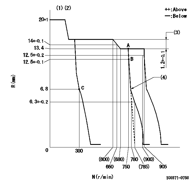
N:Pump speed
R:Rack position (mm)
(1)Target notch: K
(2)Tolerance for racks not indicated: +-0.05mm.
(3)Rack difference between N = N1 and N = N2
(4)Idle sub spring setting: L1.
----------
K=11 N1=750r/min N2=500r/min L1=7.3+-0.1mm
----------
----------
K=11 N1=750r/min N2=500r/min L1=7.3+-0.1mm
----------
Speed control lever angle
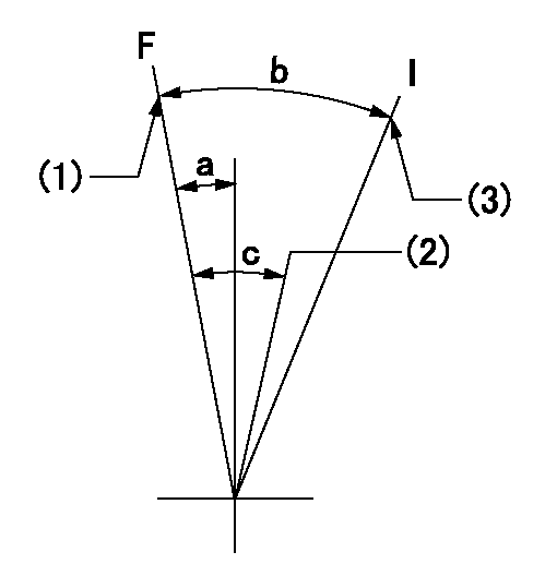
F:Full speed
I:Idle
(1)Set the pump speed at aa. ( At delivery )
(2)Set the pump speed at bb.
(3)Stopper bolt setting
----------
aa=905r/min bb=750r/min
----------
a=4deg+-5deg b=33deg+-5deg c=8deg+-5deg
----------
aa=905r/min bb=750r/min
----------
a=4deg+-5deg b=33deg+-5deg c=8deg+-5deg
Stop lever angle

N:Pump normal
S:Stop the pump.
(1)Normal
----------
----------
a=26deg+-5deg b=53deg+-5deg
----------
----------
a=26deg+-5deg b=53deg+-5deg
0000001501 GOV FULL LOAD ADJUSTMENT
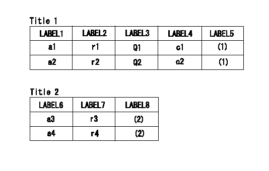
Title1:Full load stopper adjustment
Title2:Governor set speed
LABEL1:Distinguishing
LABEL2:Pump speed (r/min)
LABEL3:Ave. injection quantity (mm3/st)
LABEL4:Max. var. bet. cyl.
LABEL5:Remarks
LABEL6:Distinguishing
LABEL7:Governor set speed (r/min)
LABEL8:Remarks
(1)Adjustment conditions are the same as those for measuring injection quantity.
(2)-
----------
----------
a1=E a2=A r1=750r/min r2=750r/min Q1=177.2+-2mm3/st Q2=157.4+-2mm3/st c1=+-4% c2=+-4% a3=18 a4=15 r3=950r/min r4=750r/min
----------
----------
a1=E a2=A r1=750r/min r2=750r/min Q1=177.2+-2mm3/st Q2=157.4+-2mm3/st c1=+-4% c2=+-4% a3=18 a4=15 r3=950r/min r4=750r/min
Timing setting

(1)Pump vertical direction
(2)Position of the gear's standard threaded installation hole at the start of injection for the No. 10 cylinder.
(3)-
(4)-
----------
----------
a=(50deg)
----------
----------
a=(50deg)
Information:
Setting rack(4) Setting governor (setting maximum speed )(a) While applying the full load to the engine, hold the speed control lever in the specified maximum speed position.(b) Adjust the governor setting bolt (maximum speed setting bolt) to the specified speed position, and set it there.
Setting governor(5) Setting torque spring (optional specification)Set the speed control lever at the maximum speed, and apply the load to the engine. Turn the torque spring adjusting screw until the engine delivers the specified output at the specified speed. Fix the screw with the locknut, and install a cap to the lock nut.
Setting torque spring(6) Measuring speed variationMeasurement of speed variation at removal of load.(a) Operate the speed control to set the engine at the rated output and speed.(b) From this condition, instantaneously remove the load to put the engine into the no-load condition. Operate the engine with the speed control lever fixed.(c) The engine speed temporarily jumps up then lowers and stabilizes. Record the momentary maximum speed, stabilized speed, and time from the removal of the load to the stabilization of the speed.Measurement of speed variation at application of load.From the no-load condition, instantaneously apply the specified load to the engine. Record the momentary maximum speed, stabilized speed, and time from the application of the load to the stabilization of the speed.Calculation of speed variationCalculate the speed variation from the measured results. When the speed variation falls outside specified limits, adjust the governor notches.
Measuring speed variation(7) Adjusting speed variation (adjusting governor notches)(a) Adjust the speed variation by turning the adjusting screw of the swivel lever.(b) Remove the plug at the top of the governor, and set the speed control lever to the low idle speed position. The swivel lever turns up to reveal the head of the adjusting screw. Turn the adjusting screw with a flat-head screwdriver.(c) The speed variation decreases as the adjusting screw is tightened and increases as the adjusting screw is loosened. One notch equals a quarter turn of the adjusting screw and changes the engine speed by three to five revolutions.(d) Turning the adjusting screw changes the governor spring tension and hence the maximum speed. Readjust the governor setting bolt.(e) The maximum speed increases as the adjusting screw is tightened and decreases as the adjusting screw is loosened.
The adjusting screw can be loosened by 20 notches (or five turns) from the position where it is fully tightened. It is dangerous if the adjusting screw is loosened more.
Adjusting speed variation(8) SealingSeal each setting bolt.Break-in Operation
When the engine is overhauled, it should be mounted on a dynamometer and operated for break-in and inspection.Starting Up
(1) Before starting the engine, check the levels of coolant, engine oil and fuel, and bleed the fuel and cooling system.(2) With the fuel supply cut off, operate the starter and crank the engine for about 15 seconds to circulate engine oil.(3) Move the speed control lever slightly in the direction for increased fuel (do not move it to "full injection" position), and then turn the starter switch
Have questions with 106971-0750?
Group cross 106971-0750 ZEXEL
Nissan-Diesel
Nissan-Diesel
Nissan-Diesel
Nissan-Diesel
106971-0750
INJECTION-PUMP ASSEMBLY