Information injection-pump assembly
ZEXEL
106971-0650
1069710650

Rating:
Service parts 106971-0650 INJECTION-PUMP ASSEMBLY:
1.
_
6.
COUPLING PLATE
7.
COUPLING PLATE
8.
_
9.
_
11.
Nozzle and Holder
1660097013
12.
Open Pre:MPa(Kqf/cm2)
22.6(230)
15.
NOZZLE SET
Include in #1:
106971-0650
as INJECTION-PUMP ASSEMBLY
Cross reference number
ZEXEL
106971-0650
1069710650
Zexel num
Bosch num
Firm num
Name
106971-0650
INJECTION-PUMP ASSEMBLY
Calibration Data:
Adjustment conditions
Test oil
1404 Test oil ISO4113 or {SAEJ967d}
1404 Test oil ISO4113 or {SAEJ967d}
Test oil temperature
degC
40
40
45
Nozzle and nozzle holder
105780-8140
Bosch type code
EF8511/9A
Nozzle
105780-0000
Bosch type code
DN12SD12T
Nozzle holder
105780-2080
Bosch type code
EF8511/9
Opening pressure
MPa
17.2
Opening pressure
kgf/cm2
175
Injection pipe
Outer diameter - inner diameter - length (mm) mm 8-3-600
Outer diameter - inner diameter - length (mm) mm 8-3-600
Overflow valve opening pressure
kPa
157
123
191
Overflow valve opening pressure
kgf/cm2
1.6
1.25
1.95
Tester oil delivery pressure
kPa
157
157
157
Tester oil delivery pressure
kgf/cm2
1.6
1.6
1.6
Direction of rotation (viewed from drive side)
Right R
Right R
Injection timing adjustment
Direction of rotation (viewed from drive side)
Right R
Right R
Injection order
10-9-4-3
-6-5-8-7
-2-1
Pre-stroke
mm
3
2.95
3.05
Beginning of injection position
Governor side NO.1
Governor side NO.1
Difference between angles 1
Cal 10-9 deg. 45 44.5 45.5
Cal 10-9 deg. 45 44.5 45.5
Difference between angles 2
Cal 10-4 deg. 72 71.5 72.5
Cal 10-4 deg. 72 71.5 72.5
Difference between angles 3
Cal 10-3 deg. 117 116.5 117.5
Cal 10-3 deg. 117 116.5 117.5
Difference between angles 4
Cal 10-6 deg. 144 143.5 144.5
Cal 10-6 deg. 144 143.5 144.5
Difference between angles 5
Cal 10-5 deg. 189 188.5 189.5
Cal 10-5 deg. 189 188.5 189.5
Difference between angles 6
Cal 10-8 deg. 216 215.5 216.5
Cal 10-8 deg. 216 215.5 216.5
Difference between angles 7
Cal 10-7 deg. 261 260.5 261.5
Cal 10-7 deg. 261 260.5 261.5
Difference between angles 8
Cal 10-2 deg. 288 287.5 288.5
Cal 10-2 deg. 288 287.5 288.5
Difference between angles 9
Cal 10-1 deg. 333 332.5 333.5
Cal 10-1 deg. 333 332.5 333.5
Injection quantity adjustment
Adjusting point
A
Rack position
12.7
Pump speed
r/min
775
775
775
Average injection quantity
mm3/st.
160.1
159.1
161.1
Max. variation between cylinders
%
0
-4
4
Basic
*
Fixing the lever
*
Boost pressure
kPa
82.6
82.6
Boost pressure
mmHg
620
620
Injection quantity adjustment_02
Adjusting point
B
Rack position
12.1
Pump speed
r/min
1000
1000
1000
Average injection quantity
mm3/st.
141.8
137.8
145.8
Max. variation between cylinders
%
0
-4
4
Fixing the lever
*
Boost pressure
kPa
82.6
82.6
Boost pressure
mmHg
620
620
Injection quantity adjustment_03
Adjusting point
C
Rack position
11.1
Pump speed
r/min
500
500
500
Average injection quantity
mm3/st.
124.1
120.1
128.1
Max. variation between cylinders
%
0
-4
4
Fixing the lever
*
Boost pressure
kPa
0
0
0
Boost pressure
mmHg
0
0
0
Injection quantity adjustment_04
Adjusting point
D
Rack position
6.9+-0.5
Pump speed
r/min
340
340
340
Average injection quantity
mm3/st.
15.3
13.3
17.3
Max. variation between cylinders
%
0
-10
10
Fixing the rack
*
Boost pressure
kPa
0
0
0
Boost pressure
mmHg
0
0
0
Boost compensator adjustment
Pump speed
r/min
600
600
600
Rack position
11.1
Boost pressure
kPa
33.3
28
38.6
Boost pressure
mmHg
250
210
290
Boost compensator adjustment_02
Pump speed
r/min
600
600
600
Rack position
12.7
Boost pressure
kPa
73.3
70.6
76
Boost pressure
mmHg
550
530
570
Timer adjustment
Pump speed
r/min
750--
Advance angle
deg.
0
0
0
Remarks
Start
Start
Timer adjustment_02
Pump speed
r/min
700
Advance angle
deg.
0.5
Timer adjustment_03
Pump speed
r/min
1000
Advance angle
deg.
1.5
1
2
Timer adjustment_04
Pump speed
r/min
-
Advance angle
deg.
3.5
3.5
3.5
Remarks
Measure the actual speed, stop
Measure the actual speed, stop
Test data Ex:
Governor adjustment
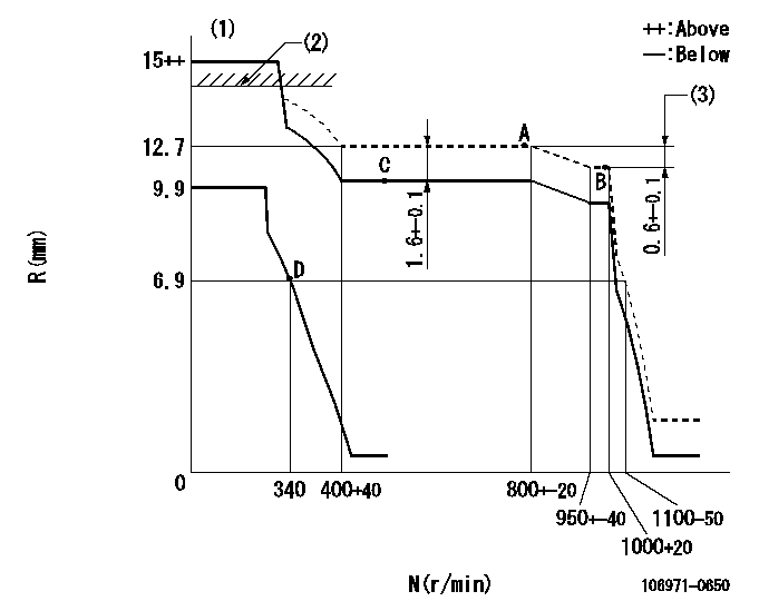
N:Pump speed
R:Rack position (mm)
(1)Target notch: K
(2)RACK LIMIT: RAL
(3)Rack difference between N = N1 and N = N2
----------
K=10 RAL=14.5+-0.1mm N1=1000r/min N2=775r/min
----------
----------
K=10 RAL=14.5+-0.1mm N1=1000r/min N2=775r/min
----------
Speed control lever angle

F:Full speed
I:Idle
(1)Stopper bolt setting
----------
----------
a=9deg+-5deg b=29deg+-5deg
----------
----------
a=9deg+-5deg b=29deg+-5deg
Stop lever angle

N:Pump normal
S:Stop the pump.
----------
----------
a=16.5deg+-5deg b=50deg+-5deg
----------
----------
a=16.5deg+-5deg b=50deg+-5deg
Timing setting

(1)Pump vertical direction
(2)Position of the gear's standard threaded installation hole at the start of injection for the No. 10 cylinder.
(3)-
(4)-
----------
----------
a=(50deg)
----------
----------
a=(50deg)
Information:
Service Standards
Tightening Torque List
Tightening Torques For Main Fasteners
"Wet" means that the threads of the relevant item should be coated with engine oil before tightening.The items whose torque specifications are marked with asterisks (*) must be tightened using special tools in order that the torque may be controlled precisely.Tightening Torques for Standard Bolts and Nuts
a. The table above applies only to standardized bolts and nuts.b. All torques shown assume use of spring washer together with bolts and nuts.c. All bolts and nuts appearing in this manual should be tightened according to this table unless otherwise indicated.d. Standard bolts and nuts should be tightened in "dry" condition, without lubricating their threads with oil.Tightening Torques for Standard Eye Bolts (for Dry Condition)
Tightening Torques for Standard Union Nuts (for Dry Condition)
Tightening Torques for Taper Screws
Sealant
Have questions with 106971-0650?
Group cross 106971-0650 ZEXEL
Nissan-Diesel
Nissan-Diesel
Nissan-Diesel
Nissan-Diesel
106971-0650
INJECTION-PUMP ASSEMBLY