Information injection-pump assembly
ZEXEL
106971-0600
1069710600

Rating:
Service parts 106971-0600 INJECTION-PUMP ASSEMBLY:
1.
_
6.
COUPLING PLATE
7.
COUPLING PLATE
8.
_
9.
_
11.
Nozzle and Holder
1660097005
12.
Open Pre:MPa(Kqf/cm2)
22.6(230)
15.
NOZZLE SET
Include in #1:
106971-0600
as INJECTION-PUMP ASSEMBLY
Cross reference number
ZEXEL
106971-0600
1069710600
Zexel num
Bosch num
Firm num
Name
106971-0600
INJECTION-PUMP ASSEMBLY
Calibration Data:
Adjustment conditions
Test oil
1404 Test oil ISO4113 or {SAEJ967d}
1404 Test oil ISO4113 or {SAEJ967d}
Test oil temperature
degC
40
40
45
Nozzle and nozzle holder
105780-8140
Bosch type code
EF8511/9A
Nozzle
105780-0000
Bosch type code
DN12SD12T
Nozzle holder
105780-2080
Bosch type code
EF8511/9
Opening pressure
MPa
17.2
Opening pressure
kgf/cm2
175
Injection pipe
Outer diameter - inner diameter - length (mm) mm 8-3-600
Outer diameter - inner diameter - length (mm) mm 8-3-600
Overflow valve opening pressure
kPa
157
123
191
Overflow valve opening pressure
kgf/cm2
1.6
1.25
1.95
Tester oil delivery pressure
kPa
157
157
157
Tester oil delivery pressure
kgf/cm2
1.6
1.6
1.6
Direction of rotation (viewed from drive side)
Right R
Right R
Injection timing adjustment
Direction of rotation (viewed from drive side)
Right R
Right R
Injection order
10-9-4-3
-6-5-8-7
-2-1
Pre-stroke
mm
3
2.95
3.05
Beginning of injection position
Governor side NO.1
Governor side NO.1
Difference between angles 1
Cal 10-9 deg. 45 44.5 45.5
Cal 10-9 deg. 45 44.5 45.5
Difference between angles 2
Cal 10-4 deg. 72 71.5 72.5
Cal 10-4 deg. 72 71.5 72.5
Difference between angles 3
Cal 10-3 deg. 117 116.5 117.5
Cal 10-3 deg. 117 116.5 117.5
Difference between angles 4
Cal 10-6 deg. 144 143.5 144.5
Cal 10-6 deg. 144 143.5 144.5
Difference between angles 5
Cal 10-5 deg. 189 188.5 189.5
Cal 10-5 deg. 189 188.5 189.5
Difference between angles 6
Cal 10-8 deg. 216 215.5 216.5
Cal 10-8 deg. 216 215.5 216.5
Difference between angles 7
Cal 10-7 deg. 261 260.5 261.5
Cal 10-7 deg. 261 260.5 261.5
Difference between angles 8
Cal 10-2 deg. 288 287.5 288.5
Cal 10-2 deg. 288 287.5 288.5
Difference between angles 9
Cal 10-1 deg. 333 332.5 333.5
Cal 10-1 deg. 333 332.5 333.5
Injection quantity adjustment
Adjusting point
A
Rack position
13.3
Pump speed
r/min
750
750
750
Average injection quantity
mm3/st.
165
163
167
Max. variation between cylinders
%
0
-4
4
Basic
*
Fixing the lever
*
Injection quantity adjustment_02
Adjusting point
B
Rack position
11.9
Pump speed
r/min
750
750
750
Average injection quantity
mm3/st.
132.6
130.6
134.6
Max. variation between cylinders
%
0
-4
4
Fixing the rack
*
Injection quantity adjustment_03
Adjusting point
C
Rack position
7.3+-0.5
Pump speed
r/min
300
300
300
Average injection quantity
mm3/st.
17.8
15.8
19.8
Max. variation between cylinders
%
0
-10
10
Fixing the rack
*
Timer adjustment
Pump speed
r/min
500+-50
Advance angle
deg.
0
0
0
Remarks
Start
Start
Timer adjustment_02
Pump speed
r/min
750
Advance angle
deg.
1.4
0.9
1.9
Timer adjustment_03
Pump speed
r/min
900
Advance angle
deg.
2.3
1.8
2.8
Timer adjustment_04
Pump speed
r/min
-
Advance angle
deg.
3.5
3.5
3.5
Remarks
Measure the actual speed, stop
Measure the actual speed, stop
Test data Ex:
Governor adjustment
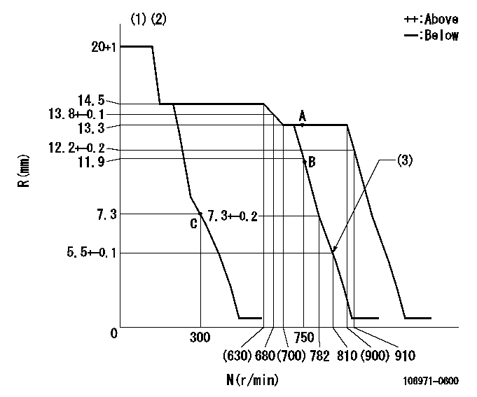
N:Pump speed
R:Rack position (mm)
(1)Target notch: K
(2)Tolerance for racks not indicated: +-0.05mm.
(3)Set idle sub-spring
----------
K=10
----------
----------
K=10
----------
Speed control lever angle
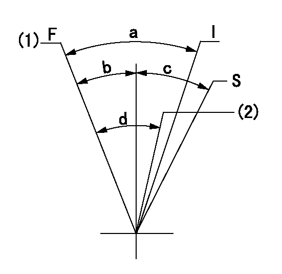
F:Full speed
I:Idle
S:Stop
(1)Set the pump speed at aa
(2)Set the pump speed at bb.
----------
aa=900r/min bb=750r/min
----------
a=27deg+-5deg b=4deg+-5deg c=32deg+-3deg d=7deg+-5deg
----------
aa=900r/min bb=750r/min
----------
a=27deg+-5deg b=4deg+-5deg c=32deg+-3deg d=7deg+-5deg
Stop lever angle

N:Pump normal
S:Stop the pump.
(1)Normal
----------
----------
a=26deg+-5deg b=53deg+-5deg
----------
----------
a=26deg+-5deg b=53deg+-5deg
0000001501 GOV FULL LOAD ADJUSTMENT
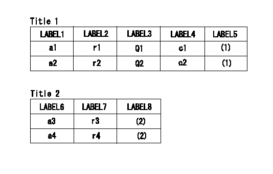
Title1:Full load stopper adjustment
Title2:Governor set speed
LABEL1:Distinguishing
LABEL2:Pump speed (r/min)
LABEL3:Ave. injection quantity (mm3/st)
LABEL4:Max. var. bet. cyl.
LABEL5:Remarks
LABEL6:Distinguishing
LABEL7:Governor set speed (r/min)
LABEL8:Remarks
(1)Adjustment conditions are the same as those for measuring injection quantity.
(2)-
----------
----------
a1=A a2=E r1=750r/min r2=750r/min Q1=165+-2mm3/st Q2=180+-2mm3/st c1=+-4% c2=+-4% a3=18 a4=15 r3=900r/min r4=750r/min
----------
----------
a1=A a2=E r1=750r/min r2=750r/min Q1=165+-2mm3/st Q2=180+-2mm3/st c1=+-4% c2=+-4% a3=18 a4=15 r3=900r/min r4=750r/min
Information:
2. Removing Accessories
(1) Removing Fan(a) Reduce the tension applied by the tension pulley by pushing the alternator toward the engine, then remove the water pump drive belt (1).(b) Remove the fan mounting bolts (2), then remove the fan (3).(c) Remove the water pump pulley (4), which was previously retained by the fan mounting bolts (2).(2) Removing Thermostat FittingRemove the water outlet fitting (1), then remove the thermostat (2), thermostat fitting (3), water joint (4), and temperature joint (5) in that sequence. (3) Removing Exhaust and Intake Manifolds(a) Remove the exhaust manifold mounting bolts, then remove the exhaust manifold (1) and the gasket (2).(b) Remove the intake manifold mounting bolts, then remove the intake manifold (3) and the gasket (4). When refitting the manifolds, fit each gasket with the side marked "MANIFOLD" facing the manifold. (4) Removing Water PumpRemove the water pump mounting bolts, then remove the water pump (1). (5) Removing Alternator(a) Disconnect the battery cables.(b) Disconnect the lead from terminal B at the rear of the alternator.(c) Remove the alternator connector.(d) Loosen the alternator brace bolt (1) and support bolt (2), then push the alternator toward the engine and remove the fan belt.(e) Remove the alternator. (6) Removing Starter(a) Disconnect the battery's (-) and (+) terminals in that sequence.(b) Disconnect the start wiring (1).(c) Remove the starter's two mounting bolts (2), then remove the starter (3). (7) Removing Oil Filter(a) The oil filter (2) must be replaced every 100 hours of use.(b) Remove the oil filter using a filter wrench (1). (8) Removing Fuel Filter(a) Remove the fuel pipe (1) that leads from the fuel tank and the fuel pipe (2) that leads to the fuel pump.(b) Remove the fuel filter (3) from the engine. (9) Removing Fuel Pipes(a) Remove the clamps from the four fuel pipes (1), then disconnect the fuel pipes from the engine and from the injection pump.(b) Remove the joints and clips from the fuel hose (2), then disconnect the fuel hose from the injector holders.
To keep dirt out of the fuel system, fit rubber caps over the parts of the injection pump and injector inlet connectors from which the injection pipes are disconnected.
(10) Removing Injection Pump
1 Fuel hose2 Fuel pipe3 Tie rod cover4 Tie rod spring5 Tie rod6 Injection pump7 Adjustment shim8 Control rack pin(a) Remove the tie rod cover (3).
Removing tie rod cover(b) Using long-nosed pliers, remove the tie rod spring (4) from the control rack pin (8) and from the governor lever pin.(c) Remove the tie rod (5).
Removing tie rod(d) Remove the injection pump (6) and the adjustment shim (7).
Removing injection pump(11) Removing Oil PumpRemove the oil pump's four mounting bolts, then remove the oil pump (1). (12) Removing InjectorDisconnect the fuel injection pipe (1) and the fuel hose (2) before removing the injector (3). 3. Refitting Accessories
3.1 General PointsRefit accessories by following the removal procedures in reverse. After refitting accessories, perform the following operations:(1) Pour the specified amount of engine oil into the engine.(2) Pour coolant into the cooling
Have questions with 106971-0600?
Group cross 106971-0600 ZEXEL
106971-0600
INJECTION-PUMP ASSEMBLY