Information injection-pump assembly
BOSCH
9 400 618 637
9400618637
ZEXEL
106971-0584
1069710584
NISSAN-DIESEL
1671397105
1671397105
Rating:
Compare Prices: .
As an associate, we earn commssions on qualifying purchases through the links below

4317943 Refrigerator Ice Maker Replacement for Kenmore/Sears 106.9710584 - Compatible with W10190952 Icemaker
UpStart Components UpStart Components Replacement 4317943 Refrigerator Ice Maker for Kenmore / Sears 106.9710584 || Ultra durable, high quality material resists wear and tear over time. Easy at-home installation. || An affordable way to extend the life of your machine. || Please make sure to check your original part to confirm that you are buying the correct product. || Compatible W10190952 Icemaker for Part Number 4317943, AP2984633, 4317943R, 4317943VP, 46000978556, 46004211173, AH358591, EA358591, ER4317943, J21791, J22241, M626687, PS358591, RIM943, TJ90RIM943, W10122496, W10190952, W10281545, W10632400
UpStart Components UpStart Components Replacement 4317943 Refrigerator Ice Maker for Kenmore / Sears 106.9710584 || Ultra durable, high quality material resists wear and tear over time. Easy at-home installation. || An affordable way to extend the life of your machine. || Please make sure to check your original part to confirm that you are buying the correct product. || Compatible W10190952 Icemaker for Part Number 4317943, AP2984633, 4317943R, 4317943VP, 46000978556, 46004211173, AH358591, EA358591, ER4317943, J21791, J22241, M626687, PS358591, RIM943, TJ90RIM943, W10122496, W10190952, W10281545, W10632400
Service parts 106971-0584 INJECTION-PUMP ASSEMBLY:
1.
_
7.
COUPLING PLATE
8.
_
9.
_
11.
Nozzle and Holder
1660097064
12.
Open Pre:MPa(Kqf/cm2)
14.7(150)/21.6(220)

15.
NOZZLE SET
Include in #1:
106971-0584
as INJECTION-PUMP ASSEMBLY
Cross reference number
BOSCH
9 400 618 637
9400618637
ZEXEL
106971-0584
1069710584
NISSAN-DIESEL
1671397105
1671397105
Zexel num
Bosch num
Firm num
Name
106971-0584
9 400 618 637
1671397105 NISSAN-DIESEL
INJECTION-PUMP ASSEMBLY
RF10 * K
RF10 * K
Calibration Data:
Adjustment conditions
Test oil
1404 Test oil ISO4113 or {SAEJ967d}
1404 Test oil ISO4113 or {SAEJ967d}
Test oil temperature
degC
40
40
45
Nozzle and nozzle holder
105780-8140
Bosch type code
EF8511/9A
Nozzle
105780-0000
Bosch type code
DN12SD12T
Nozzle holder
105780-2080
Bosch type code
EF8511/9
Opening pressure
MPa
17.2
Opening pressure
kgf/cm2
175
Injection pipe
Outer diameter - inner diameter - length (mm) mm 8-3-600
Outer diameter - inner diameter - length (mm) mm 8-3-600
Overflow valve opening pressure
kPa
157
123
191
Overflow valve opening pressure
kgf/cm2
1.6
1.25
1.95
Tester oil delivery pressure
kPa
157
157
157
Tester oil delivery pressure
kgf/cm2
1.6
1.6
1.6
Direction of rotation (viewed from drive side)
Right R
Right R
Injection timing adjustment
Direction of rotation (viewed from drive side)
Right R
Right R
Injection order
10-9-4-3
-6-5-8-7
-2-1
Pre-stroke
mm
3.65
3.6
3.7
Beginning of injection position
Governor side NO.1
Governor side NO.1
Difference between angles 1
Cal 10-9 deg. 45 44.5 45.5
Cal 10-9 deg. 45 44.5 45.5
Difference between angles 2
Cal 10-4 deg. 72 71.5 72.5
Cal 10-4 deg. 72 71.5 72.5
Difference between angles 3
Cal 10-3 deg. 117 116.5 117.5
Cal 10-3 deg. 117 116.5 117.5
Difference between angles 4
Cal 10-6 deg. 144 143.5 144.5
Cal 10-6 deg. 144 143.5 144.5
Difference between angles 5
Cal 10-5 deg. 189 188.5 189.5
Cal 10-5 deg. 189 188.5 189.5
Difference between angles 6
Cal 10-8 deg. 216 215.5 216.5
Cal 10-8 deg. 216 215.5 216.5
Difference between angles 7
Cal 10-7 deg. 261 260.5 261.5
Cal 10-7 deg. 261 260.5 261.5
Difference between angles 8
Cal 10-2 deg. 288 287.5 288.5
Cal 10-2 deg. 288 287.5 288.5
Difference between angles 9
Cal 10-1 deg. 333 332.5 333.5
Cal 10-1 deg. 333 332.5 333.5
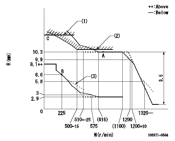
Injection quantity adjustment
Adjusting point
A
Rack position
10.3
Pump speed
r/min
650
650
650
Average injection quantity
mm3/st.
132.4
131.4
133.4
Max. variation between cylinders
%
0
-4
4
Basic
*
Fixing the lever
*
Injection quantity adjustment_02
Adjusting point
B
Rack position
6.6+-0.5
Pump speed
r/min
225
225
225
Average injection quantity
mm3/st.
13.6
11.6
15.6
Max. variation between cylinders
%
0
-10
10
Fixing the rack
*
Injection quantity adjustment_03
Adjusting point
C
Rack position
11.8+0.2
Pump speed
r/min
40
40
40
Average injection quantity
mm3/st.
115
105
125
Fixing the lever
*
Rack limit
*
Timer adjustment
Pump speed
r/min
950--
Advance angle
deg.
0
0
0
Load
3/4
Remarks
Start
Start
Timer adjustment_02
Pump speed
r/min
900
Advance angle
deg.
0.5
Load
3/4
Timer adjustment_03
Pump speed
r/min
1100
Advance angle
deg.
4
3.5
4.5
Load
4/4
Remarks
Finish
Finish
Test data Ex:
Governor adjustment
N:Pump speed
R:Rack position (mm)
(1)Rack limit using the stop lever: R1
(2)Excess fuel setting for starting: SXL
(3)Damper spring setting: DL
----------
R1=11.8+0.2mm SXL=10.3+0.2mm DL=6.1-0.2mm
----------
----------
R1=11.8+0.2mm SXL=10.3+0.2mm DL=6.1-0.2mm
----------
Speed control lever angle

F:Full speed
----------
----------
a=8deg+-5deg
----------
----------
a=8deg+-5deg
0000000901
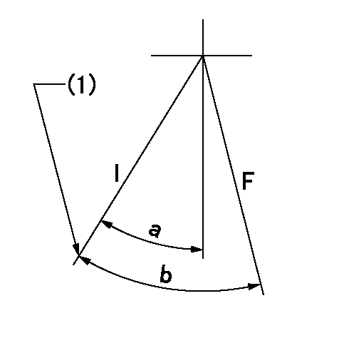
F:Full load
I:Idle
(1)Stopper bolt setting
----------
----------
a=18.5deg+-5deg b=27.5deg+-3deg
----------
----------
a=18.5deg+-5deg b=27.5deg+-3deg
Stop lever angle
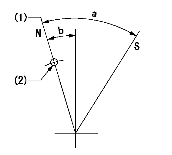
N:Pump normal
S:Stop the pump.
(1)Rack position = aa
(2)Use the hole at R = bb
----------
aa=11.8+0.2mm bb=32mm
----------
a=30.5deg+-5deg b=5deg+-5deg
----------
aa=11.8+0.2mm bb=32mm
----------
a=30.5deg+-5deg b=5deg+-5deg
Timing setting

(1)Pump vertical direction
(2)Position of the coupling's key groove at the start of injection for the No. 10 cylinder.
(3)-
(4)-
----------
----------
a=(90deg)
----------
----------
a=(90deg)
Information:
1. Overview
1.1 External Views 1.2 Engine Model and Engine Serial Number(1) The engine model code is embossed next to the injection pump on the right-hand side of the cylinder block.
Engine model and total displacement(2) The engine serial number is shown by a label attached to the top of the rocker cover. It is also stamped on the injection pump mounting surface of the cylinder block.(3) The engine serial number is stamped as shown below:
Location of engine serial number label1.3 Engine Model and Application Codes(1) The engine model code is designated as shown below.* Engine model and classification * Model code 2. Specifications
2.1 Major Specifications 3. Points to Note for Disassembly and Reassembly
This service manual contains recommended service procedures for your Mitsubishi diesel engine. It also contains information on special tools and basic safety precautions. Since hazards exist in many places, the safety precautions in this manual should not be considered exhaustive. It is your responsibility to exercise common sense and to pay attention to safety at all times.Always perform service operations in accordance with this manual. When performing disassembly and reassembly operations, also observe the general instructions given below.3.1 Disassembly(1) Use only the correct tools and instruments.(2) Use an overhaul stand or work bench if necessary, and make ready a surface where removed parts can be arranged. Remove parts in the specified disassembly sequence.(3) Arrange disassembled parts neatly to avoid losing them.(4) Pay attention to alignment and position marks. If necessary, make your own marks to facilitate reassembly.(5) Carefully check parts for abnormalities when removing or cleaning them. Abnormalities may be harder to see after parts have been removed or cleaned.(6) Strive to ensure safety at all times. It is particularly important to make sure that items being disassembled are properly balanced and to pay attention to safety when moving heavy items. Use jacks and chain blocks when necessary.3.2 Reassembly(1) Wash all engine parts (except oil seals, O-rings, and rubber seals) in cleaning solvent and dry them with compressed air.(2) Use only the correct tools and instruments.(3) Use only high-quality oils and greases of the specified types. Be sure to apply a coat of oil, grease, or sealant wherever specified.(4) Use a torque wrench to achieve all specified tightening torques.(5) As a general rule, all gaskets and seals must be replaced with new ones. Apply adhesive where required, and be careful not to apply too much.
Have questions with 106971-0584?
Group cross 106971-0584 ZEXEL
Nissan-Diesel
Nissan-Diesel
Nissan-Diesel
Nissan-Diesel
Nissan-Diesel
Nissan-Diesel
Nissan-Diesel
Nissan-Diesel
Nissan-Diesel
106971-0584
9 400 618 637
1671397105
INJECTION-PUMP ASSEMBLY
RF10
RF10