Information injection-pump assembly
ZEXEL
106971-0580
1069710580
Rating:
Service parts 106971-0580 INJECTION-PUMP ASSEMBLY:
1.
_
7.
COUPLING PLATE
8.
_
9.
_
11.
Nozzle and Holder
16600-97064
12.
Open Pre:MPa(Kqf/cm2)
14.7{150}/21.6{220}

15.
NOZZLE SET
Include in #1:
106971-0580
as INJECTION-PUMP ASSEMBLY
Cross reference number
ZEXEL
106971-0580
1069710580
Zexel num
Bosch num
Firm num
Name
Calibration Data:
Adjustment conditions
Test oil
1404 Test oil ISO4113 or {SAEJ967d}
1404 Test oil ISO4113 or {SAEJ967d}
Test oil temperature
degC
40
40
45
Nozzle and nozzle holder
105780-8140
Bosch type code
EF8511/9A
Nozzle
105780-0000
Bosch type code
DN12SD12T
Nozzle holder
105780-2080
Bosch type code
EF8511/9
Opening pressure
MPa
17.2
Opening pressure
kgf/cm2
175
Injection pipe
Outer diameter - inner diameter - length (mm) mm 8-3-600
Outer diameter - inner diameter - length (mm) mm 8-3-600
Overflow valve opening pressure
kPa
157
123
191
Overflow valve opening pressure
kgf/cm2
1.6
1.25
1.95
Tester oil delivery pressure
kPa
157
157
157
Tester oil delivery pressure
kgf/cm2
1.6
1.6
1.6
Direction of rotation (viewed from drive side)
Right R
Right R
Injection timing adjustment
Direction of rotation (viewed from drive side)
Right R
Right R
Injection order
10-9-4-3
-6-5-8-7
-2-1
Pre-stroke
mm
3.65
3.6
3.7
Beginning of injection position
Governor side NO.1
Governor side NO.1
Difference between angles 1
Cal 10-9 deg. 45 44.5 45.5
Cal 10-9 deg. 45 44.5 45.5
Difference between angles 2
Cal 10-4 deg. 72 71.5 72.5
Cal 10-4 deg. 72 71.5 72.5
Difference between angles 3
Cal 10-3 deg. 117 116.5 117.5
Cal 10-3 deg. 117 116.5 117.5
Difference between angles 4
Cal 10-6 deg. 144 143.5 144.5
Cal 10-6 deg. 144 143.5 144.5
Difference between angles 5
Cal 10-5 deg. 189 188.5 189.5
Cal 10-5 deg. 189 188.5 189.5
Difference between angles 6
Cal 10-8 deg. 216 215.5 216.5
Cal 10-8 deg. 216 215.5 216.5
Difference between angles 7
Cal 10-7 deg. 261 260.5 261.5
Cal 10-7 deg. 261 260.5 261.5
Difference between angles 8
Cal 10-2 deg. 288 287.5 288.5
Cal 10-2 deg. 288 287.5 288.5
Difference between angles 9
Cal 10-1 deg. 333 332.5 333.5
Cal 10-1 deg. 333 332.5 333.5
Injection quantity adjustment
Adjusting point
A
Rack position
10.3
Pump speed
r/min
650
650
650
Average injection quantity
mm3/st.
132.4
131.4
133.4
Max. variation between cylinders
%
0
-4
4
Basic
*
Fixing the lever
*
Injection quantity adjustment_02
Adjusting point
B
Rack position
6.6+-0.5
Pump speed
r/min
225
225
225
Average injection quantity
mm3/st.
13.6
11.6
15.6
Max. variation between cylinders
%
0
-10
10
Fixing the rack
*
Timer adjustment
Pump speed
r/min
950--
Advance angle
deg.
0
0
0
Load
3/4
Remarks
Start
Start
Timer adjustment_02
Pump speed
r/min
900
Advance angle
deg.
0.5
Load
3/4
Timer adjustment_03
Pump speed
r/min
1100
Advance angle
deg.
4
3.5
4.5
Load
4/4
Remarks
Finish
Finish
Test data Ex:
Governor adjustment
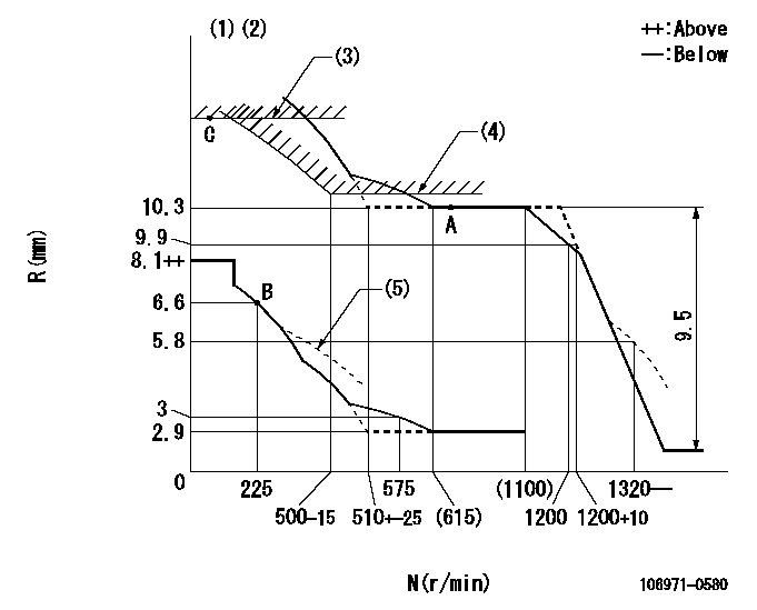
N:Pump speed
R:Rack position (mm)
(1)Lever ratio: RT
(2)Target shim dimension: TH
(3)Rack limit using the stop lever: R1
(4)Excess fuel setting for starting: SXL
(5)Damper spring setting: DL
----------
RT=1 TH=1.6mm R1=11.8+0.2mm SXL=10.3+0.2mm DL=6.1-0.2mm
----------
----------
RT=1 TH=1.6mm R1=11.8+0.2mm SXL=10.3+0.2mm DL=6.1-0.2mm
----------
Speed control lever angle

F:Full speed
----------
----------
a=8deg+-5deg
----------
----------
a=8deg+-5deg
0000000901

F:Full load
I:Idle
(1)Stopper bolt setting
----------
----------
a=18.5deg+-5deg b=27.5deg+-3deg
----------
----------
a=18.5deg+-5deg b=27.5deg+-3deg
Stop lever angle
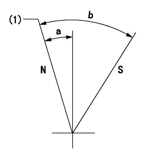
N:Pump normal
S:Stop the pump.
(1)Rack position = aa
----------
aa=11.8+0.2mm
----------
a=5deg+-5deg b=30.5deg+-5deg
----------
aa=11.8+0.2mm
----------
a=5deg+-5deg b=30.5deg+-5deg
Timing setting

(1)Pump vertical direction
(2)Position of the coupling's key groove at the start of injection for the No. 10 cylinder.
(3)-
(4)-
----------
----------
a=(90deg)
----------
----------
a=(90deg)
Information:
3. Inspection
Inspection points4. Assembly
Assembly sequenceFollow the reverse of disassembly and use the procedure that follows. Assembly procedure (1) Barrel installationPut each barrel in position in the housing with its slot in alignment with the dowel of the housing and put it straight down into the bore. If the slot in the barrel is not aligned with the dowel of the housing, the O-ring will not seat correctly (still visible) after the delivery valve holder has been installed.
Installing barrels(2) Delivery valve installationInstall the delivery valve, gasket, spring and O-ring on the barrel and tighten the delivery valve holder finger tight. Do this step for remainder of the delivery valves.
a) Any time the injection pump is disassembled, a new O-ring must be installed.b) Make sure the threads of the delivery valve holder do not cause damage to the O-rings.
Installing delivery valves(3) Control sleeve installation (a) Install each control sleeve with the center tooth in alignment with the line mark of the control rack.
Installing control sleeves(b) Put the plungers in position in the barrels.
Make sure the notch in the plunger is toward the adjusting plate.
Installing plungers(4) Tappet installationMove the control rack back and forth while pushing down on each tappet to align the slot in the tappet with the hole in the housing for the tappet guide pin. Install the lock plates and tappet guide pins in position.
Any time the injection pump is disassembled, new lock plates must be used.
Installing tappets(5) Delivery valve holder installation Put the delivery valve holders in position and tighten them to the specified torque.
Do not over tighten the delivery valve holders. This can put end force on the barrels, resulting in a failure of the plungers to move freely. If the holders are not tightened to the specified torque, engine oil would leak in the injection pump.
Tightening delivery valve holders(6) Inspection after assembly (a) After the injection pump has been assembled, check to see if the control rack moves freely without any binding or catching.(b) If the control rack fails to move freely, the possible causes are:1) Pumping element(s) sticking2) Foreign particles lodged between control rack and sleeves3) Over-tightening of delivery valve holder(s)Disassemble and check the injection pump to locate the cause of the trouble. (c) After the injection pump has been finally assembled, check the injection timing.
Checking control rack movementGOVERNOR
1. Disassembly and inspection
Disassembly sequence and inspection points1 Tie rod spring2 Tie rod3 Speed control lever4 Spring pin5 Grooved pin6 Governor shaft (Remove 7 thru 11 as an assembly.)7 Governor lever8 Start spring9 Tension lever10 Governor spring11 Governor spring lever12 Governor case2. Assembly (1) Install the levers in position.
Installing governor levers(2) Put O-ring on the governor shaft. (3) Put the governor shaft in position in the governor case and put the levers on the governor shaft. (4) Install the grooved pin and spring pin in position with a hammer.(5) Install the tie rod and tie rod spring in position.
Assembling governor3. Torque spring set installation The torque spring set is to be installed and adjusted after an