Information injection-pump assembly
BOSCH
9 400 618 635
9400618635
ZEXEL
106971-0552
1069710552
NISSAN-DIESEL
1671397103
1671397103

Rating:
Service parts 106971-0552 INJECTION-PUMP ASSEMBLY:
1.
_
7.
COUPLING PLATE
8.
_
9.
_
11.
Nozzle and Holder
12.
Open Pre:MPa(Kqf/cm2)
19.6(200)

15.
NOZZLE SET
Include in #1:
106971-0552
as INJECTION-PUMP ASSEMBLY
Cross reference number
BOSCH
9 400 618 635
9400618635
ZEXEL
106971-0552
1069710552
NISSAN-DIESEL
1671397103
1671397103
Zexel num
Bosch num
Firm num
Name
106971-0552
9 400 618 635
1671397103 NISSAN-DIESEL
INJECTION-PUMP ASSEMBLY
RE10 * K 14CE INJECTION PUMP ASSY PE10P PE
RE10 * K 14CE INJECTION PUMP ASSY PE10P PE
Calibration Data:
Adjustment conditions
Test oil
1404 Test oil ISO4113 or {SAEJ967d}
1404 Test oil ISO4113 or {SAEJ967d}
Test oil temperature
degC
40
40
45
Nozzle and nozzle holder
105780-8140
Bosch type code
EF8511/9A
Nozzle
105780-0000
Bosch type code
DN12SD12T
Nozzle holder
105780-2080
Bosch type code
EF8511/9
Opening pressure
MPa
17.2
Opening pressure
kgf/cm2
175
Injection pipe
Outer diameter - inner diameter - length (mm) mm 8-3-600
Outer diameter - inner diameter - length (mm) mm 8-3-600
Overflow valve opening pressure
kPa
157
123
191
Overflow valve opening pressure
kgf/cm2
1.6
1.25
1.95
Tester oil delivery pressure
kPa
157
157
157
Tester oil delivery pressure
kgf/cm2
1.6
1.6
1.6
Direction of rotation (viewed from drive side)
Right R
Right R
Injection timing adjustment
Direction of rotation (viewed from drive side)
Right R
Right R
Injection order
10-9-4-3
-6-5-8-7
-2-1
Pre-stroke
mm
3.65
3.6
3.65
Beginning of injection position
Governor side NO.1
Governor side NO.1
Difference between angles 1
Cal 10-9 deg. 45 44.5 45.5
Cal 10-9 deg. 45 44.5 45.5
Difference between angles 2
Cal 10-4 deg. 72 71.5 72.5
Cal 10-4 deg. 72 71.5 72.5
Difference between angles 3
Cal 10-3 deg. 117 116.5 117.5
Cal 10-3 deg. 117 116.5 117.5
Difference between angles 4
Cal 10-6 deg. 144 143.5 144.5
Cal 10-6 deg. 144 143.5 144.5
Difference between angles 5
Cal 10-5 deg. 189 188.5 189.5
Cal 10-5 deg. 189 188.5 189.5
Difference between angles 6
Cal 10-8 deg. 216 215.5 216.5
Cal 10-8 deg. 216 215.5 216.5
Difference between angles 7
Cal 10-7 deg. 261 260.5 261.5
Cal 10-7 deg. 261 260.5 261.5
Difference between angles 8
Cal 10-2 deg. 288 287.5 288.5
Cal 10-2 deg. 288 287.5 288.5
Difference between angles 9
Cal 10-1 deg. 333 332.5 333.5
Cal 10-1 deg. 333 332.5 333.5
Injection quantity adjustment
Adjusting point
A
Rack position
10.2
Pump speed
r/min
700
700
700
Average injection quantity
mm3/st.
105.2
104.2
106.2
Max. variation between cylinders
%
0
-4
4
Basic
*
Fixing the lever
*
Injection quantity adjustment_02
Adjusting point
B
Rack position
5.7+-0.5
Pump speed
r/min
250
250
250
Average injection quantity
mm3/st.
11.9
9.9
13.9
Max. variation between cylinders
%
0
-10
10
Fixing the rack
*
Timer adjustment
Pump speed
r/min
550
Advance angle
deg.
0.5
Timer adjustment_02
Pump speed
r/min
700
Advance angle
deg.
1
0.5
1.5
Timer adjustment_03
Pump speed
r/min
1150
Advance angle
deg.
5.5
5
6
Remarks
Finish
Finish
Test data Ex:
Governor adjustment
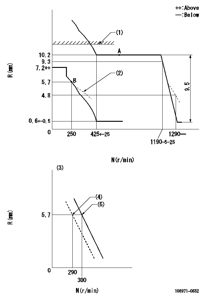
N:Pump speed
R:Rack position (mm)
(1)Rack limit using stop lever: R1 (at N = N1 or less).
(2)Damper spring setting: DL
(3)Variable speed specification: idling adjustment
(4)Main spring setting
(5)Set idle sub-spring
----------
R1=10.6+0.2mm N1=100r/min DL=5.7-0.2mm
----------
----------
R1=10.6+0.2mm N1=100r/min DL=5.7-0.2mm
----------
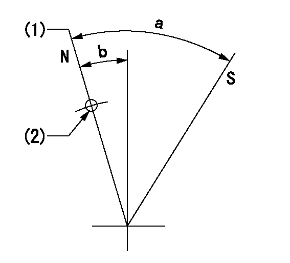
Speed control lever angle

F:Full speed
I:Idle
(1)Stopper bolt setting
----------
----------
a=9.5deg+-5deg b=19.5deg+-5deg
----------
----------
a=9.5deg+-5deg b=19.5deg+-5deg
0000000901

F:Full load
I:Idle
(1)Stopper bolt setting
----------
----------
a=24.5deg+-5deg b=35.5deg+-3deg
----------
----------
a=24.5deg+-5deg b=35.5deg+-3deg
Stop lever angle
N:Pump normal
S:Stop the pump.
(1)Rack position = aa
(2)Use the hole at R = bb
----------
aa=10.6+0.2mm bb=32mm
----------
a=27.5deg+-5deg b=2deg+-5deg
----------
aa=10.6+0.2mm bb=32mm
----------
a=27.5deg+-5deg b=2deg+-5deg
Timing setting

(1)Pump vertical direction
(2)Position of the coupling's key groove at the start of injection for the No. 10 cylinder.
(3)-
(4)-
----------
----------
a=(90deg)
----------
----------
a=(90deg)
Information:
The front plate is bolted inside the timing gear case. Do not attempt to remove this plate along with the timing gear case by tapping.
Front plate attaching bolts8. Timing gear backlash measurement Measure the backlash of each gear and keep a record of it for correct installation. Replace the gears if the backlash exceeds the limit.
Unit: mm (in.)
Measuring timing gear backlash9. Idler gear removal To remove the idler gear, rotate the gear in a direction of the helix of the teeth to pull it out of mesh.
Removing idler gear10. Camshaft removal (1) Remove the bolts that hold the thrust plate. (2) Pull the camshaft out of the cylinder block.
Do not cause damage to the lobes or bearing journals when removing the camshaft.
Removing camshaft11. Fuel injection pump camshaft removal(1) Remove the stopper bolt.
Removing camshaft stopper bolt(2) Tap the rear end of the camshaft with a copper bar to push it out of the front side of the cylinder block.
Removing fuel injection pump camshaft12. Gear removal (when required) To remove the gears from the camshaft and fuel injection pump camshaft, use an arbor press.13. Oil pump removal Remove the bolts that hold the oil pump to the cylinder block and remove the pump.
Removing oil pump14. Front plate removal Remove four bolts that hold the front plate in position. Tap the plate lightly with a plastic hammer to separate the gasket.
Removing front plateCYLINDER BLOCK, CRANKSHAFT, PISTONS AND OIL PAN
1 Oil pan2 Oil screen3 Connecting rod cap4 Connecting rod bearing (lower half) (Remove 5 thru 10 as an assembly.)5 Connecting rod6 Piston pin7 No. 1 ring8 No. 2 ring9 Oil ring10 Piston11 Connecting rod bearing (upper half)12 Main bearing cap13 Main bearing (lower half)14 Crankshaft15 Main bearing (upper half)16 Cylinder block When the cylinder block is to be discarded, remove the components (pressure relief valve, etc.) from the block for reuse. 1. Oil pan removal (1) Turn the engine upside down.(2) Tap the bottom corners of the oil pan with a plastic hammer to remove the oil pan.
Do not attempt to pry off the oil pan by inserting a screwdriver or a chisel between the oil pan and cylinder block. Damage to the oil pan can be the result.
Removing oil pan2. Oil screen removal Loosen the nut that holds the oil screen in position and remove the screen.
Removing oil screen3. Thrust clearance measurement for connecting rod big endInstall the connecting rod to its crankpin and tighten the cap nuts to the specified torque. Measure the thrust clearance with a feeler gauge. If the clearance exceeds the limit, replace the connecting rod.
Measuring thrust clearance for connecting rod big end
Unit: mm (in.)4. Connecting rod cap removal (1) Lay the cylinder block on its side.(2) Put identification on each connecting rod and cap combination as to its location in the engine.(3) Remove the caps.
Removing connecting rod caps5. Piston removal (1) Turn the crankshaft until the piston is at top center. (2) Push the piston and connecting rod away from the crankshaft with the handle of
Have questions with 106971-0552?
Group cross 106971-0552 ZEXEL
Nissan-Diesel
Nissan-Diesel
Nissan-Diesel
Nissan-Diesel
Nissan-Diesel
Nissan-Diesel
Nissan-Diesel
106971-0552
9 400 618 635
1671397103
INJECTION-PUMP ASSEMBLY
RE10
RE10