Information injection-pump assembly
BOSCH
9 400 618 634
9400618634
ZEXEL
106971-0543
1069710543
NISSAN-DIESEL
1670097104
1670097104
Rating:
Service parts 106971-0543 INJECTION-PUMP ASSEMBLY:
1.
_
7.
COUPLING PLATE
8.
_
9.
_
11.
Nozzle and Holder
12.
Open Pre:MPa(Kqf/cm2)
19.6(200)

15.
NOZZLE SET
Include in #1:
106971-0543
as INJECTION-PUMP ASSEMBLY
Cross reference number
BOSCH
9 400 618 634
9400618634
ZEXEL
106971-0543
1069710543
NISSAN-DIESEL
1670097104
1670097104
Zexel num
Bosch num
Firm num
Name
106971-0543
9 400 618 634
1670097104 NISSAN-DIESEL
INJECTION-PUMP ASSEMBLY
RE10 * K
RE10 * K
Calibration Data:
Adjustment conditions
Test oil
1404 Test oil ISO4113 or {SAEJ967d}
1404 Test oil ISO4113 or {SAEJ967d}
Test oil temperature
degC
40
40
45
Nozzle and nozzle holder
105780-8140
Bosch type code
EF8511/9A
Nozzle
105780-0000
Bosch type code
DN12SD12T
Nozzle holder
105780-2080
Bosch type code
EF8511/9
Opening pressure
MPa
17.2
Opening pressure
kgf/cm2
175
Injection pipe
Outer diameter - inner diameter - length (mm) mm 8-3-600
Outer diameter - inner diameter - length (mm) mm 8-3-600
Overflow valve opening pressure
kPa
157
123
191
Overflow valve opening pressure
kgf/cm2
1.6
1.25
1.95
Tester oil delivery pressure
kPa
157
157
157
Tester oil delivery pressure
kgf/cm2
1.6
1.6
1.6
Direction of rotation (viewed from drive side)
Right R
Right R
Injection timing adjustment
Direction of rotation (viewed from drive side)
Right R
Right R
Injection order
10-9-4-3
-6-5-8-7
-2-1
Pre-stroke
mm
3.65
3.6
3.7
Beginning of injection position
Governor side NO.1
Governor side NO.1
Difference between angles 1
Cal 10-9 deg. 45 44.5 45.5
Cal 10-9 deg. 45 44.5 45.5
Difference between angles 2
Cal 10-4 deg. 72 71.5 72.5
Cal 10-4 deg. 72 71.5 72.5
Difference between angles 3
Cal 10-3 deg. 117 116.5 117.5
Cal 10-3 deg. 117 116.5 117.5
Difference between angles 4
Cal 10-6 deg. 144 143.5 144.5
Cal 10-6 deg. 144 143.5 144.5
Difference between angles 5
Cal 10-5 deg. 189 188.5 189.5
Cal 10-5 deg. 189 188.5 189.5
Difference between angles 6
Cal 10-8 deg. 216 215.5 216.5
Cal 10-8 deg. 216 215.5 216.5
Difference between angles 7
Cal 10-7 deg. 261 260.5 261.5
Cal 10-7 deg. 261 260.5 261.5
Difference between angles 8
Cal 10-2 deg. 288 287.5 288.5
Cal 10-2 deg. 288 287.5 288.5
Difference between angles 9
Cal 10-1 deg. 333 332.5 333.5
Cal 10-1 deg. 333 332.5 333.5
Injection quantity adjustment
Adjusting point
A
Rack position
10.2
Pump speed
r/min
700
700
700
Average injection quantity
mm3/st.
105.2
104.2
106.2
Max. variation between cylinders
%
0
-4
4
Basic
*
Fixing the lever
*
Injection quantity adjustment_02
Adjusting point
B
Rack position
5.7+-0.5
Pump speed
r/min
225
225
225
Average injection quantity
mm3/st.
11.3
9.3
13.3
Max. variation between cylinders
%
0
-10
10
Fixing the rack
*
Timer adjustment
Pump speed
r/min
550
Advance angle
deg.
0.5
Timer adjustment_02
Pump speed
r/min
700
Advance angle
deg.
1
0.5
1.5
Timer adjustment_03
Pump speed
r/min
1150
Advance angle
deg.
5.5
5
6
Remarks
Finish
Finish
Test data Ex:
Governor adjustment
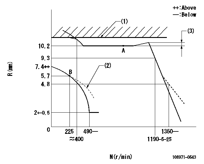
N:Pump speed
R:Rack position (mm)
(1)Rack limit using the stop lever: R1
(2)Damper spring setting: DL
(3)Rack difference from N = N1
----------
R1=10.6+0.2mm DL=5.7-0.2mm N1=700r/min
----------
----------
R1=10.6+0.2mm DL=5.7-0.2mm N1=700r/min
----------
0000000901

F:Full load
I:Idle
(1)Stopper bolt setting
----------
----------
a=16deg+-5deg b=17deg+-3deg
----------
----------
a=16deg+-5deg b=17deg+-3deg
Stop lever angle
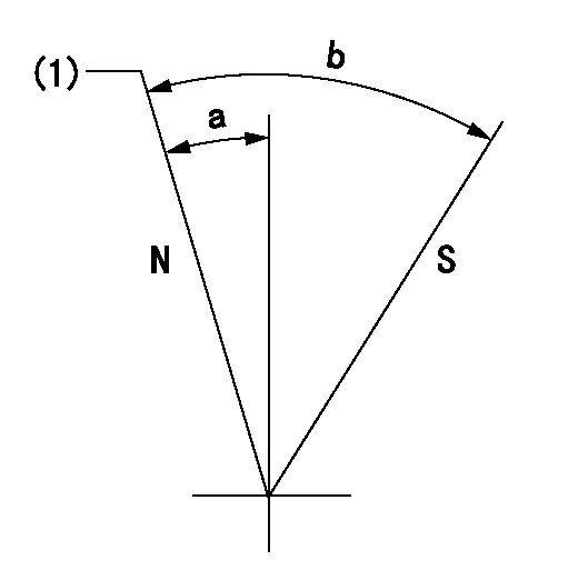
N:Pump normal
S:Stop the pump.
(1)Rack position = aa
----------
aa=10.6+0.2mm
----------
a=12deg+-5deg b=31deg+-5deg
----------
aa=10.6+0.2mm
----------
a=12deg+-5deg b=31deg+-5deg
Timing setting

(1)Pump vertical direction
(2)Position of the coupling's key groove at the start of injection for the No. 10 cylinder.
(3)-
(4)-
----------
----------
a=(90deg)
----------
----------
a=(90deg)
Information:
05Apr2010
U-111
A-90
D-97
O-103
TT-8
TM-6
TA-4
Parts stock action only
PRODUCT IMPROVEMENT PROGRAM FOR THE INSPECTION AND POSSIBLE REMOVAL OF 4P-9830 FUEL PUMP PLUNGER AND BARREL ASSEMBLIES AND 4P-9827 FUEL INJECTION PUMP GROUPS IN DEALER PARTS STOCK
7750 PI70339
When submitting claim for Parts Stock Action, Use the appropriate 99Z as the s/n, the appropriate Service Letter Program Number as the Part number in the Part Causing Failure field, "7751" as the Group Number, "56" as the Description Code.
The information supplied in this service letter may not be valid after the termination date of this program.Do not perform the work outlined in this Service Letter after the termination date without first contacting your Caterpillar product analyst.
TERMINATION DATE
31Jul2010
PROBLEM
Some 4P-9830 Plunger and Barrel assemblies, and 4P-9827 Pump Groups may be incorrectly calibrated.
ACTION REQUIRED
Inspect the date code on all 4P-9830 Plunger and Barrel Assemblies, and all 4P-9827 Pump Groups in dealer parts stock. (Refer to Image1 for date code location example.)
- If the date code on the package is before D02M03Y10P478 (Day 02, Month 03, Year 10; 02 March 2010), remove the part from dealers part stock.
- If the date code on the package is on or after D02M03Y10P478 (Day 02, Month 03, Year 10; 02 March 2010), mark the package to indicate it has been inpected according to this program and return it to dealer parts stock.
Image1
SERVICE CLAIM ALLOWANCES
Submit one claim for all parts removed from dealer parts stock.
PARTS DISPOSITION
Handle the parts in accordance with your Warranty Bulletin on warranty parts handling.
A Send-It-Back Part Return Request (PRR) will be generated when the claim is submitted using this program (PI7####) as the part causing failure.
Have questions with 106971-0543?
Group cross 106971-0543 ZEXEL
Nissan-Diesel
Nissan-Diesel
Nissan-Diesel
Nissan-Diesel
Nissan-Diesel
Nissan-Diesel
106971-0543
9 400 618 634
1670097104
INJECTION-PUMP ASSEMBLY
RE10
RE10