Information injection-pump assembly
ZEXEL
106971-0500
1069710500
Rating:
Service parts 106971-0500 INJECTION-PUMP ASSEMBLY:
1.
_
7.
COUPLING PLATE
8.
_
9.
_
11.
Nozzle and Holder
16600-97064
12.
Open Pre:MPa(Kqf/cm2)
14.7{150}/21.6{220}

15.
NOZZLE SET
Include in #1:
106971-0500
as INJECTION-PUMP ASSEMBLY
Cross reference number
ZEXEL
106971-0500
1069710500
Zexel num
Bosch num
Firm num
Name
Calibration Data:
Adjustment conditions
Test oil
1404 Test oil ISO4113 or {SAEJ967d}
1404 Test oil ISO4113 or {SAEJ967d}
Test oil temperature
degC
40
40
45
Nozzle and nozzle holder
105780-8140
Bosch type code
EF8511/9A
Nozzle
105780-0000
Bosch type code
DN12SD12T
Nozzle holder
105780-2080
Bosch type code
EF8511/9
Opening pressure
MPa
17.2
Opening pressure
kgf/cm2
175
Injection pipe
Outer diameter - inner diameter - length (mm) mm 8-3-600
Outer diameter - inner diameter - length (mm) mm 8-3-600
Overflow valve opening pressure
kPa
157
123
191
Overflow valve opening pressure
kgf/cm2
1.6
1.25
1.95
Tester oil delivery pressure
kPa
157
157
157
Tester oil delivery pressure
kgf/cm2
1.6
1.6
1.6
Direction of rotation (viewed from drive side)
Right R
Right R
Injection timing adjustment
Direction of rotation (viewed from drive side)
Right R
Right R
Injection order
10-9-4-3
-6-5-8-7
-2-1
Pre-stroke
mm
3.65
3.6
3.7
Beginning of injection position
Governor side NO.1
Governor side NO.1
Difference between angles 1
Cal 10-9 deg. 45 44.5 45.5
Cal 10-9 deg. 45 44.5 45.5
Difference between angles 2
Cal 10-4 deg. 72 71.5 72.5
Cal 10-4 deg. 72 71.5 72.5
Difference between angles 3
Cal 10-3 deg. 117 116.5 117.5
Cal 10-3 deg. 117 116.5 117.5
Difference between angles 4
Cal 10-6 deg. 144 143.5 144.5
Cal 10-6 deg. 144 143.5 144.5
Difference between angles 5
Cal 10-5 deg. 189 188.5 189.5
Cal 10-5 deg. 189 188.5 189.5
Difference between angles 6
Cal 10-8 deg. 216 215.5 216.5
Cal 10-8 deg. 216 215.5 216.5
Difference between angles 7
Cal 10-7 deg. 261 260.5 261.5
Cal 10-7 deg. 261 260.5 261.5
Difference between angles 8
Cal 10-2 deg. 288 287.5 288.5
Cal 10-2 deg. 288 287.5 288.5
Difference between angles 9
Cal 10-1 deg. 333 332.5 333.5
Cal 10-1 deg. 333 332.5 333.5
Injection quantity adjustment
Adjusting point
A
Rack position
10.3
Pump speed
r/min
650
650
650
Average injection quantity
mm3/st.
132.4
131.4
133.4
Max. variation between cylinders
%
0
-4
4
Basic
*
Fixing the lever
*
Injection quantity adjustment_02
Adjusting point
B
Rack position
6.6+-0.5
Pump speed
r/min
225
225
225
Average injection quantity
mm3/st.
13.6
11.6
15.6
Max. variation between cylinders
%
0
-10
10
Fixing the rack
*
Timer adjustment
Pump speed
r/min
950--
Advance angle
deg.
0
0
0
Load
3/4
Remarks
Start
Start
Timer adjustment_02
Pump speed
r/min
900
Advance angle
deg.
0.5
Load
3/4
Timer adjustment_03
Pump speed
r/min
1100
Advance angle
deg.
4
3.5
4.5
Load
4/4
Remarks
Finish
Finish
Test data Ex:
Governor adjustment
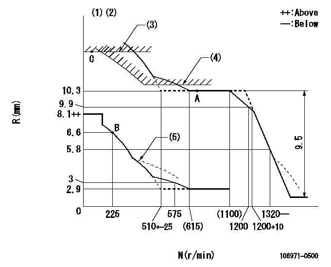
N:Pump speed
R:Rack position (mm)
(1)Lever ratio: RT
(2)Target shim dimension: TH
(3)Rack limit using the stop lever: R1
(4)Excess fuel setting for starting: SXL
(5)Damper spring setting: DL
----------
RT=1 TH=1.6mm R1=11.8+0.2mm SXL=10.3+0.2mm DL=5.6-0.2mm
----------
----------
RT=1 TH=1.6mm R1=11.8+0.2mm SXL=10.3+0.2mm DL=5.6-0.2mm
----------
Speed control lever angle

F:Full speed
----------
----------
a=8deg+-5deg
----------
----------
a=8deg+-5deg
0000000901

F:Full load
I:Idle
(1)Stopper bolt setting
----------
----------
a=18.5deg+-5deg b=27.5deg+-3deg
----------
----------
a=18.5deg+-5deg b=27.5deg+-3deg
Stop lever angle

N:Pump normal
S:Stop the pump.
(1)Rack position = aa
----------
aa=11.8+0.2mm
----------
a=5deg+-5deg b=30.5deg+-5deg
----------
aa=11.8+0.2mm
----------
a=5deg+-5deg b=30.5deg+-5deg
Timing setting

(1)Pump vertical direction
(2)Position of the coupling's key groove at the start of injection for the No. 10 cylinder.
(3)-
(4)-
----------
----------
a=(90deg)
----------
----------
a=(90deg)
Information:
Thermostat Removal
Stop engine.Disconnect negative (-) battery cable at battery.
Do not drain engine coolant until the coolant temperature is below operating temperature. Then loosen drain cock slowly to relieve any excess pressure.
Remove coolant from cooling system.
Fig. 1-Thermostat CoverDisconnect upper radiator hose from thermostat cover (Fig. 1).Remove thermostat cover.Remove gasket.
Fig. 2-ThermostatLift thermostat (Fig. 2) out of thermostat housing.Repair
Fig. 3-Thermostat OpenIf engine is running too hot or too cold inspect thermostat for defects. Test in hot water for proper opening and closing.Installation
Some thermostats are marked "TO RAD", "THIS SIDE TOWARD RADIATOR", or "TOWARD RADIATOR" to indicate the top side. Put thermostat in housing so that top side is toward thermostat cover.
Fig. 4-Top SideIf thermostat is not marked, find the top side (Fig. 4). Put thermostat in housing so that top side is toward thermostat cover.
Fig. 5-Cap ScrewUsing a new gasket, install thermostat cover. Put cap screws (Fig. 5) through thermostat cover into thermostat housing. Tighten cap screws to 35 lb-ft (47 N m) (5 kg-m).Connect upper radiator hose to thermostat cover.Fill cooling system to proper level with proper coolant.Connect negative (-) battery cable to battery negative (-) terminal.Start engine.Check for leaks at hose connection and around gasket area.