Information injection-pump assembly
BOSCH
9 400 618 625
9400618625
ZEXEL
106971-0446
1069710446
NISSAN-DIESEL
1671397101
1671397101
Rating:
Service parts 106971-0446 INJECTION-PUMP ASSEMBLY:
1.
_
7.
COUPLING PLATE
8.
_
9.
_
11.
Nozzle and Holder
1660097066
12.
Open Pre:MPa(Kqf/cm2)
14.7(150)/19.6(200)

15.
NOZZLE SET
Include in #1:
106971-0446
as INJECTION-PUMP ASSEMBLY
Cross reference number
BOSCH
9 400 618 625
9400618625
ZEXEL
106971-0446
1069710446
NISSAN-DIESEL
1671397101
1671397101
Zexel num
Bosch num
Firm num
Name
106971-0446
9 400 618 625
1671397101 NISSAN-DIESEL
INJECTION-PUMP ASSEMBLY
RE10 * K
RE10 * K
Calibration Data:
Adjustment conditions
Test oil
1404 Test oil ISO4113 or {SAEJ967d}
1404 Test oil ISO4113 or {SAEJ967d}
Test oil temperature
degC
40
40
45
Nozzle and nozzle holder
105780-8140
Bosch type code
EF8511/9A
Nozzle
105780-0000
Bosch type code
DN12SD12T
Nozzle holder
105780-2080
Bosch type code
EF8511/9
Opening pressure
MPa
17.2
Opening pressure
kgf/cm2
175
Injection pipe
Outer diameter - inner diameter - length (mm) mm 8-3-600
Outer diameter - inner diameter - length (mm) mm 8-3-600
Overflow valve opening pressure
kPa
157
123
191
Overflow valve opening pressure
kgf/cm2
1.6
1.25
1.95
Tester oil delivery pressure
kPa
157
157
157
Tester oil delivery pressure
kgf/cm2
1.6
1.6
1.6
Direction of rotation (viewed from drive side)
Right R
Right R
Injection timing adjustment
Direction of rotation (viewed from drive side)
Right R
Right R
Injection order
10-9-4-3
-6-5-8-7
-2-1
Pre-stroke
mm
3.65
3.6
3.7
Beginning of injection position
Governor side NO.1
Governor side NO.1
Difference between angles 1
Cal 10-9 deg. 45 44.5 45.5
Cal 10-9 deg. 45 44.5 45.5
Difference between angles 2
Cal 10-4 deg. 72 71.5 72.5
Cal 10-4 deg. 72 71.5 72.5
Difference between angles 3
Cal 10-3 deg. 117 116.5 117.5
Cal 10-3 deg. 117 116.5 117.5
Difference between angles 4
Cal 10-6 deg. 144 143.5 144.5
Cal 10-6 deg. 144 143.5 144.5
Difference between angles 5
Cal 10-5 deg. 189 188.5 189.5
Cal 10-5 deg. 189 188.5 189.5
Difference between angles 6
Cal 10-8 deg. 216 215.5 216.5
Cal 10-8 deg. 216 215.5 216.5
Difference between angles 7
Cal 10-7 deg. 261 260.5 261.5
Cal 10-7 deg. 261 260.5 261.5
Difference between angles 8
Cal 10-2 deg. 288 287.5 288.5
Cal 10-2 deg. 288 287.5 288.5
Difference between angles 9
Cal 10-1 deg. 333 332.5 333.5
Cal 10-1 deg. 333 332.5 333.5
Injection quantity adjustment
Adjusting point
A
Rack position
9.3
Pump speed
r/min
700
700
700
Average injection quantity
mm3/st.
111.5
110.5
112.5
Max. variation between cylinders
%
0
-4
4
Basic
*
Fixing the lever
*
Injection quantity adjustment_02
Adjusting point
B
Rack position
8.5
Pump speed
r/min
1200
1200
1200
Average injection quantity
mm3/st.
105.2
103.2
107.2
Max. variation between cylinders
%
0
-4
4
Fixing the lever
*
Injection quantity adjustment_03
Adjusting point
E
Rack position
6.3+-0.5
Pump speed
r/min
225
225
225
Average injection quantity
mm3/st.
9.4
7.4
11.4
Max. variation between cylinders
%
0
-10
10
Fixing the rack
*
Timer adjustment
Pump speed
r/min
750
Advance angle
deg.
0.5
Timer adjustment_02
Pump speed
r/min
950
Advance angle
deg.
2.2
1.7
2.7
Timer adjustment_03
Pump speed
r/min
1150
Advance angle
deg.
5.5
5
6
Remarks
Finish
Finish
Test data Ex:
Governor adjustment
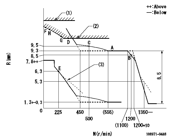
N:Pump speed
R:Rack position (mm)
(1)Rack limit using stop lever: R1 (at N = N1 or less).
(2)Excess fuel setting for starting: SXL
(3)Damper spring setting: DL
----------
R1=13.8+0.2mm N1=100r/min SXL=10.1+-0.1mm DL=5.8-0.2mm
----------
----------
R1=13.8+0.2mm N1=100r/min SXL=10.1+-0.1mm DL=5.8-0.2mm
----------
Speed control lever angle

F:Full speed
----------
----------
a=7deg+-5deg
----------
----------
a=7deg+-5deg
0000000901
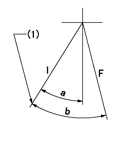
F:Full load
I:Idle
(1)Stopper bolt setting
----------
----------
a=18.5deg+-5deg b=29.5deg+-3deg
----------
----------
a=18.5deg+-5deg b=29.5deg+-3deg
Stop lever angle
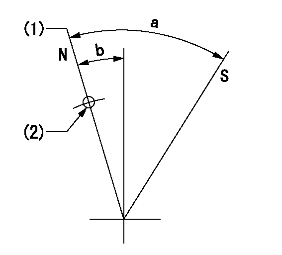
N:Pump normal
S:Stop the pump.
(1)Rack position = aa
(2)Use the hole at R = bb
----------
aa=13.8+0.2mm bb=32mm
----------
a=36deg+-5deg b=10.5deg+-5deg
----------
aa=13.8+0.2mm bb=32mm
----------
a=36deg+-5deg b=10.5deg+-5deg
Timing setting

(1)Pump vertical direction
(2)Position of the coupling's key groove at the start of injection for the No. 10 cylinder.
(3)-
(4)-
----------
----------
a=(90deg)
----------
----------
a=(90deg)
Information:
Measure wear of the cylinder bore at the top and bottom of piston ring travel.(1) Cylinder bore [standard, original size] ... 4.5005 .0005 in.(114.313 0.013 mm) The recommendation is made to make the cylinder bore the next size larger when the size of the bore is ... 4.5060 in.(114.452 mm)Cylinder bore must be made the next size larger when the size of the bore is ... 4.5090 in.(114.529 mm)Cylinder bore [.020 in. (0.51 mm) larger than the original size] ... 4.5205 .0005 in.(114.821 0.013 mm)The recommendation is made to make the cylinder bore the next size larger when the size of the bore is ... 4.5260 in.(114.960 mm)Cylinder bore must be made the next size larger when the size of the bore is ... 4.5290 in.(115.037 mm)Cylinder bore [.040 in. (1.02 mm) larger than the original size] ... 4.5405 .0005 in.(115.329 0.013 mm)Maximum permissible wear of cylinder bores (replacement of the cylinder block is necessary) ... 4.5490 in.(115.545 mm)(2) Bore in block for camshaft bearing ... 2.6525 .0005 in.(67.374 0.013 mm)(3) Width of main bearing cap ... 6.5600 .0005 in.(116.624 0.013 mm) Minimum permissible width of main bearing cap ... 6.5580 in.(116.573 mm)Width of main bearing cap guide (in cylinder block) ... 6.5590 .0005 in.(116.599 0.013 mm)(4) Bore in block for main bearing ... 3.7075 .0005 in.(94.171 0.013 mm) Permissible amount of distortion in bore ... 3.706 to 3.709 in.(94.13 to 94.21 mm)(5) Torque for bolts holding caps for main bearings: A. Put crankcase oil on bolt threads and washer face.B. Tighten all bolts by number to ... 60 15 lb. ft.(8.3 2.0 mkg)C. Again tighten all bolts by number to ... 175 10 lb. ft.(24.2 1.4 mkg)Engines with Serial Numbers 98M2494 and Up, tighten bolts (5) holding caps for main bearings in the following sequence: 1. Put crankcase oil on bolt threads and washer face.2. Tighten all bolts by number to ... 30 3 lb. ft.(4.1 0.4 mkg)3. Put a mark on each bolt and cap.4. Tighten all bolts by number from mark ... 120° 5°
Have questions with 106971-0446?
Group cross 106971-0446 ZEXEL
Nissan-Diesel
Nissan-Diesel
106971-0446
9 400 618 625
1671397101
INJECTION-PUMP ASSEMBLY
RE10
RE10