Information injection-pump assembly
ZEXEL
106971-0442
1069710442
Rating:
Service parts 106971-0442 INJECTION-PUMP ASSEMBLY:
1.
_
3.
GOVERNOR
7.
COUPLING PLATE
8.
_
9.
_
11.
Nozzle and Holder
16600-97066
12.
Open Pre:MPa(Kqf/cm2)
14.7{150}/19.6{200}

15.
NOZZLE SET
Include in #1:
106971-0442
as INJECTION-PUMP ASSEMBLY
Cross reference number
ZEXEL
106971-0442
1069710442
Zexel num
Bosch num
Firm num
Name
Calibration Data:
Adjustment conditions
Test oil
1404 Test oil ISO4113 or {SAEJ967d}
1404 Test oil ISO4113 or {SAEJ967d}
Test oil temperature
degC
40
40
45
Nozzle and nozzle holder
105780-8140
Bosch type code
EF8511/9A
Nozzle
105780-0000
Bosch type code
DN12SD12T
Nozzle holder
105780-2080
Bosch type code
EF8511/9
Opening pressure
MPa
17.2
Opening pressure
kgf/cm2
175
Injection pipe
Outer diameter - inner diameter - length (mm) mm 8-3-600
Outer diameter - inner diameter - length (mm) mm 8-3-600
Overflow valve opening pressure
kPa
157
123
191
Overflow valve opening pressure
kgf/cm2
1.6
1.25
1.95
Tester oil delivery pressure
kPa
157
157
157
Tester oil delivery pressure
kgf/cm2
1.6
1.6
1.6
Direction of rotation (viewed from drive side)
Right R
Right R
Injection timing adjustment
Direction of rotation (viewed from drive side)
Right R
Right R
Injection order
10-9-4-3
-6-5-8-7
-2-1
Pre-stroke
mm
3.65
3.6
3.7
Beginning of injection position
Governor side NO.1
Governor side NO.1
Difference between angles 1
Cal 10-9 deg. 45 44.5 45.5
Cal 10-9 deg. 45 44.5 45.5
Difference between angles 2
Cal 10-4 deg. 72 71.5 72.5
Cal 10-4 deg. 72 71.5 72.5
Difference between angles 3
Cal 10-3 deg. 117 116.5 117.5
Cal 10-3 deg. 117 116.5 117.5
Difference between angles 4
Cal 10-6 deg. 144 143.5 144.5
Cal 10-6 deg. 144 143.5 144.5
Difference between angles 5
Cal 10-5 deg. 189 188.5 189.5
Cal 10-5 deg. 189 188.5 189.5
Difference between angles 6
Cal 10-8 deg. 216 215.5 216.5
Cal 10-8 deg. 216 215.5 216.5
Difference between angles 7
Cal 10-7 deg. 261 260.5 261.5
Cal 10-7 deg. 261 260.5 261.5
Difference between angles 8
Cal 10-2 deg. 288 287.5 288.5
Cal 10-2 deg. 288 287.5 288.5
Difference between angles 9
Cal 10-1 deg. 333 332.5 333.5
Cal 10-1 deg. 333 332.5 333.5
Injection quantity adjustment
Adjusting point
A
Rack position
9.3
Pump speed
r/min
700
700
700
Average injection quantity
mm3/st.
111.5
110.5
112.5
Max. variation between cylinders
%
0
-4
4
Basic
*
Fixing the lever
*
Injection quantity adjustment_02
Adjusting point
B
Rack position
8.5
Pump speed
r/min
1200
1200
1200
Average injection quantity
mm3/st.
105.2
103.2
107.2
Max. variation between cylinders
%
0
-4
4
Fixing the lever
*
Injection quantity adjustment_03
Adjusting point
E
Rack position
6.3+-0.5
Pump speed
r/min
225
225
225
Average injection quantity
mm3/st.
9.4
7.4
11.4
Max. variation between cylinders
%
0
-10
10
Fixing the rack
*
Timer adjustment
Pump speed
r/min
800--
Advance angle
deg.
0
0
0
Remarks
Start
Start
Timer adjustment_02
Pump speed
r/min
750
Advance angle
deg.
0.5
Timer adjustment_03
Pump speed
r/min
950
Advance angle
deg.
2.2
1.7
2.7
Timer adjustment_04
Pump speed
r/min
1150
Advance angle
deg.
5.5
5
6
Remarks
Finish
Finish
Test data Ex:
Governor adjustment
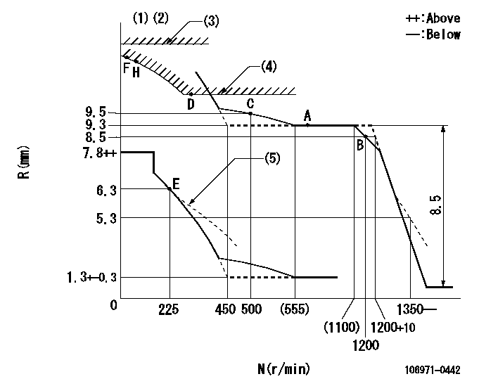
N:Pump speed
R:Rack position (mm)
(1)Lever ratio: RT
(2)Target shim dimension: TH
(3)Rack limit using stop lever: RA (at N = N1 or less).
(4)Excess fuel setting for starting: SXL
(5)Damper spring setting: DL
----------
RT=1 TH=1.8mm RA=13.8+0.2mm N1=100r/min SXL=10.1+-0.1mm DL=5.8-0.2mm
----------
----------
RT=1 TH=1.8mm RA=13.8+0.2mm N1=100r/min SXL=10.1+-0.1mm DL=5.8-0.2mm
----------
Speed control lever angle

F:Full speed
----------
----------
a=7deg+-5deg
----------
----------
a=7deg+-5deg
0000000901

F:Full load
I:Idle
(1)Stopper bolt setting
----------
----------
a=18.5deg+-5deg b=29.5deg+-3deg
----------
----------
a=18.5deg+-5deg b=29.5deg+-3deg
Stop lever angle
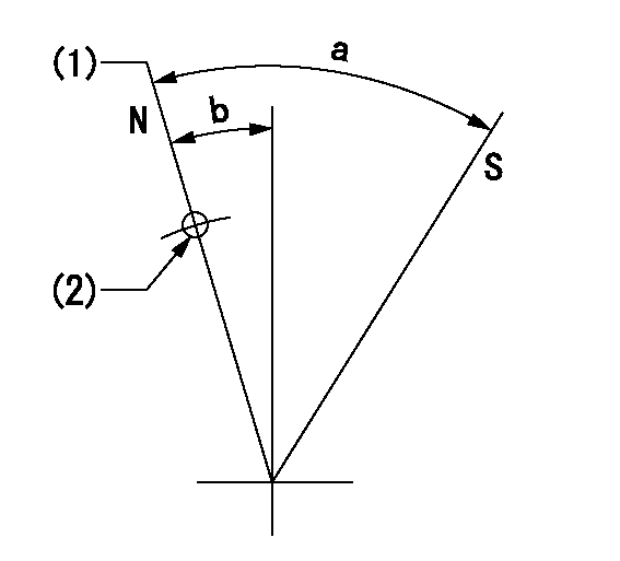
N:Pump normal
S:Stop the pump.
(1)Rack position = aa
(2)R = bb
----------
aa=13.8+0.2mm bb=32mm
----------
a=36deg+-5deg b=10.5deg+-5deg
----------
aa=13.8+0.2mm bb=32mm
----------
a=36deg+-5deg b=10.5deg+-5deg
Timing setting

(1)Pump vertical direction
(2)Position of the coupling's key groove at the start of injection for the No. 10 cylinder.
(3)-
(4)-
----------
----------
a=(90deg)
----------
----------
a=(90deg)
Information:
Starting System
Use a D.C. voltmeter to locate starting system components which do not function.Move starting control switch to energize the starter solenoid. Starter solenoid operation is audible as the starter motor pinion engages with the ring gear on the engine flywheel. The solenoid operation should also close the electric circuit to the motor. Attach one voltmeter lead to the solenoid terminal that is connected to the motor. Ground the other lead. Energize the starter solenoid and observe the voltmeter. A battery voltage reading indicates the malfunction is in the motor. It must be removed for further testing. No voltmeter reading indicates that the solenoid contacts do not close and the solenoid must be repaired or the starter pinion clearance should be adjusted.A starting motor solenoid that will not operate may not be receiving battery current. Attach one lead of the voltmeter to the solenoid battery cable connection. Ground the other lead. No voltmeter reading indicates a faulty circuit from the battery. A voltmeter reading indicates further testing is necessary.Continue the test by attaching one voltmeter lead to the starting motor solenoid small wire terminal and the other lead to ground. Observe the voltmeter and energize the starter solenoid. A voltmeter reading indicates that the malfunction is in the solenoid. No voltmeter reading indicates the starter switch or wiring is the fault.Attach one lead of the voltmeter to the starter switch battery wire terminal and ground the other lead. A voltmeter reading indicates a defective switch.A starting motor that operates too slow can be overloaded by excessive mechanical friction within the engine being started. Slow starting motor operation can also be caused by shorts, loose connections and/or excessive dirt within the motor.Pinion Clearance Adjustment (Prestolite)
There are two adjustments on this type motor. Armature end play and pinion position.Armature End Play
Adjust the end play to .005 to .030 in. (0.13 to 0.76 mm) by adding or removing thrust washers on the commutator end of the armature shaft.Pinion Position
This adjustment is accomplished in two steps.1. To adjust the pinion distance, connect the solenoid to a 12 volt battery as shown.Momentarily flash the jumper lead from the motor terminal stud of the solenoid to the terminal stud at (1) in the commutator end head to shift the solenoid and drive into the cranking position.
CONNECTIONS FOR ADJUSTING THE PINION POSITION
1. Jumper lead flashing point.Remove the jumper lead. The drive will remain in the cranking position until the battery is disconnected.Push the drive toward the commutator end of the motor to eliminate any slack movement in the linkage and measure the distance between the outside edge of the drive sleeve and the thrust washer. The distance (3) must be .02 to .05 in. (0.5 to 1.3 mm).Adjust to this dimension by turning the adjusting nut (2) in or out as required.
PINION POSITION ADJUSTMENT
2. Adjusting nut. 3. Distance.2. To test assembly of solenoid, it will be necessary to have an interference block cut to the dimensions shown.
INTERFERENCE BLOCK DIMENSIONSConnect the solenoid to 24 volts as