Information injection-pump assembly
ZEXEL
106971-0441
1069710441

Rating:
Cross reference number
ZEXEL
106971-0441
1069710441
Zexel num
Bosch num
Firm num
Name
Calibration Data:
Adjustment conditions
Test oil
1404 Test oil ISO4113 or {SAEJ967d}
1404 Test oil ISO4113 or {SAEJ967d}
Test oil temperature
degC
40
40
45
Nozzle and nozzle holder
105780-8140
Bosch type code
EF8511/9A
Nozzle
105780-0000
Bosch type code
DN12SD12T
Nozzle holder
105780-2080
Bosch type code
EF8511/9
Opening pressure
MPa
17.2
Opening pressure
kgf/cm2
175
Injection pipe
Outer diameter - inner diameter - length (mm) mm 8-3-600
Outer diameter - inner diameter - length (mm) mm 8-3-600
Overflow valve opening pressure
kPa
157
123
191
Overflow valve opening pressure
kgf/cm2
1.6
1.25
1.95
Tester oil delivery pressure
kPa
157
157
157
Tester oil delivery pressure
kgf/cm2
1.6
1.6
1.6
Direction of rotation (viewed from drive side)
Right R
Right R
Injection timing adjustment
Direction of rotation (viewed from drive side)
Right R
Right R
Injection order
10-9-4-3
-6-5-8-7
-2-1
Pre-stroke
mm
3.65
3.6
3.7
Beginning of injection position
Governor side NO.1
Governor side NO.1
Difference between angles 1
Cal 10-9 deg. 45 44.5 45.5
Cal 10-9 deg. 45 44.5 45.5
Difference between angles 2
Cal 10-4 deg. 72 71.5 72.5
Cal 10-4 deg. 72 71.5 72.5
Difference between angles 3
Cal 10-3 deg. 117 116.5 117.5
Cal 10-3 deg. 117 116.5 117.5
Difference between angles 4
Cal 10-6 deg. 144 143.5 144.5
Cal 10-6 deg. 144 143.5 144.5
Difference between angles 5
Cal 10-5 deg. 189 188.5 189.5
Cal 10-5 deg. 189 188.5 189.5
Difference between angles 6
Cal 10-8 deg. 216 215.5 216.5
Cal 10-8 deg. 216 215.5 216.5
Difference between angles 7
Cal 10-7 deg. 261 260.5 261.5
Cal 10-7 deg. 261 260.5 261.5
Difference between angles 8
Cal 10-2 deg. 288 287.5 288.5
Cal 10-2 deg. 288 287.5 288.5
Difference between angles 9
Cal 10-1 deg. 333 332.5 333.5
Cal 10-1 deg. 333 332.5 333.5
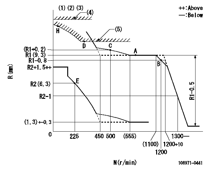
Injection quantity adjustment
Adjusting point
A
Rack position
R1(9.3)
Pump speed
r/min
700
700
700
Average injection quantity
mm3/st.
111.5
110.5
112.5
Max. variation between cylinders
%
0
-4
4
Basic
*
Fixing the lever
*
Injection quantity adjustment_02
Adjusting point
B
Rack position
R1-0.8
Pump speed
r/min
1200
1200
1200
Average injection quantity
mm3/st.
105.2
103.2
107.2
Max. variation between cylinders
%
0
-4
4
Fixing the lever
*
Injection quantity adjustment_03
Adjusting point
E
Rack position
R2(6.3)
Pump speed
r/min
225
225
225
Average injection quantity
mm3/st.
9.4
7.4
11.4
Max. variation between cylinders
%
0
-10
10
Fixing the rack
*
Injection quantity adjustment_04
Adjusting point
H
Rack position
-
Pump speed
r/min
100
100
100
Average injection quantity
mm3/st.
84
84
Fixing the lever
*
Timer adjustment
Pump speed
r/min
800--
Advance angle
deg.
0
0
0
Remarks
Start
Start
Timer adjustment_02
Pump speed
r/min
750
Advance angle
deg.
0.5
Timer adjustment_03
Pump speed
r/min
950
Advance angle
deg.
2.2
1.7
2.7
Timer adjustment_04
Pump speed
r/min
1150
Advance angle
deg.
5.5
5
6
Remarks
Finish
Finish
Test data Ex:
Governor adjustment
N:Pump speed
R:Rack position (mm)
(1)Lever ratio: RT
(2)Target shim dimension: TH
(3)Supplied with damper spring not set.
(4)Rack limit using stop lever: RA
(5)Excess fuel setting for starting: SXL
----------
RT=1 TH=2mm RA=R1+5.1+0.2mm SXL=(R1+1)mm
----------
----------
RT=1 TH=2mm RA=R1+5.1+0.2mm SXL=(R1+1)mm
----------
Speed control lever angle

F:Full speed
----------
----------
a=7deg+-5deg
----------
----------
a=7deg+-5deg
0000000901

F:Full load
I:Idle
(1)Stopper bolt setting
----------
----------
a=18.5deg+-5deg b=(29.5deg)+-3deg
----------
----------
a=18.5deg+-5deg b=(29.5deg)+-3deg
Stop lever angle
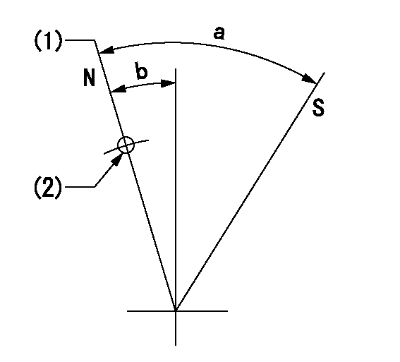
N:Pump normal
S:Stop the pump.
(1)Rack position = aa
(2)R = bb
----------
aa=R1+5.1+0.2mm bb=32mm
----------
a=(38deg)+-5deg b=(12.5deg)+-5deg
----------
aa=R1+5.1+0.2mm bb=32mm
----------
a=(38deg)+-5deg b=(12.5deg)+-5deg
Timing setting

(1)Pump vertical direction
(2)Position of the coupling's key groove at the start of injection for the No. 10 cylinder.
(3)-
(4)-
----------
----------
a=(90deg)
----------
----------
a=(90deg)
Information:
Cooling System
The centrifugal-type water pump mounts on the front cover and is belt driven by the crankshaft pulley. The pump has two outlets. Coolant from the outlet on the right side of the pump flows through a passage in the front cover to the left bank of the engine, and coolant from the outlet on the left flows to the right bank.The coolant circulates through the block to the cylinder head. Coolant flows from the heads through connecting sleeves to the return manifold in the front cover. Orifices in the sleeves control the flow from the heads.Part of the coolant to the left bank is diverted from the block to the oil cooler. External lines direct coolant from the block to the cooler and back to the return manifold in the front cover.An internal passage in the front cover directs the coolant from the return manifold to the water pump inlet. If the thermostats are closed the coolant flows to the pump and is recirculated through the engine. If they are open, coolant flows from the return manifold to the radiator and from there to the pump.The radiator is constructed with a top tank above the core and an expansion tank either above or separate from the top tank. A vent tube connects the radiator top tank and the expansion tank. The expansion tank has a shunt line which connects to the water pump inlet. This shunt system maintains a positive, static head of coolant at the pump inlet to prevent cavitation under all operating conditions. When filling the cooling system, coolant from the expansion tank flows through the shunt line to the water pump inlet and fills the engine block from the bottom. By filling the system from the bottom, air in the system is forced out through the top tank, through the vent tube into the expansion tank.The two thermostats are located at the inlet to the water pump. The inlet-regulated cooling system maintains positive coolant temperature control with decreased engine warm up time.When the thermostats are closed, coolant is circulated through the block and heads and back to the water pump by way of an internal passage in the front cover. When the thermostats are open, the bypass flow is restricted and the engine coolant flows through the radiator and returns through the inlet elbow to the water pump. Without the thermostats installed, the coolant will continually bypass the radiator, and overheating will result.Electrical System
The electrical system is a combination of three separate electric circuits: the charging circuit, the starting circuit and the lighting or load circuit. Each circuit is dependent on some of the same components. The battery (batteries), disconnect switch, circuit breaker, ammeter, cables and wires from the battery are common in each of the circuits.The charging circuit is in operation when the engine is operating. The electricity producing (charging) unit is an alternator. A regulator in the circuit senses the state of charge in the battery and regulates the electrical output to