Information injection-pump assembly
BOSCH
9 400 618 624
9400618624
ZEXEL
106971-0382
1069710382
NISSAN-DIESEL
1670097079
1670097079
Rating:
Service parts 106971-0382 INJECTION-PUMP ASSEMBLY:
1.
_
7.
COUPLING PLATE
8.
_
9.
_
10.
NOZZLE AND HOLDER ASSY
11.
Nozzle and Holder
12.
Open Pre:MPa(Kqf/cm2)
22.6(230)
15.
NOZZLE SET
Include in #1:
106971-0382
as INJECTION-PUMP ASSEMBLY
Cross reference number
BOSCH
9 400 618 624
9400618624
ZEXEL
106971-0382
1069710382
NISSAN-DIESEL
1670097079
1670097079
Zexel num
Bosch num
Firm num
Name
106971-0382
9 400 618 624
1670097079 NISSAN-DIESEL
INJECTION-PUMP ASSEMBLY
RE10 * K
RE10 * K
Calibration Data:
Adjustment conditions
Test oil
1404 Test oil ISO4113 or {SAEJ967d}
1404 Test oil ISO4113 or {SAEJ967d}
Test oil temperature
degC
40
40
45
Nozzle and nozzle holder
105780-8140
Bosch type code
EF8511/9A
Nozzle
105780-0000
Bosch type code
DN12SD12T
Nozzle holder
105780-2080
Bosch type code
EF8511/9
Opening pressure
MPa
17.2
Opening pressure
kgf/cm2
175
Injection pipe
Outer diameter - inner diameter - length (mm) mm 8-3-600
Outer diameter - inner diameter - length (mm) mm 8-3-600
Overflow valve opening pressure
kPa
157
123
191
Overflow valve opening pressure
kgf/cm2
1.6
1.25
1.95
Tester oil delivery pressure
kPa
157
157
157
Tester oil delivery pressure
kgf/cm2
1.6
1.6
1.6
Direction of rotation (viewed from drive side)
Right R
Right R
Injection timing adjustment
Direction of rotation (viewed from drive side)
Right R
Right R
Injection order
10-9-4-3
-6-5-8-7
-2-1
Pre-stroke
mm
3.65
3.6
3.7
Beginning of injection position
Governor side NO.1
Governor side NO.1
Difference between angles 1
Cal 10-9 deg. 45 44.5 45.5
Cal 10-9 deg. 45 44.5 45.5
Difference between angles 2
Cal 10-4 deg. 72 71.5 72.5
Cal 10-4 deg. 72 71.5 72.5
Difference between angles 3
Cal 10-3 deg. 117 116.5 117.5
Cal 10-3 deg. 117 116.5 117.5
Difference between angles 4
Cal 10-6 deg. 144 143.5 144.5
Cal 10-6 deg. 144 143.5 144.5
Difference between angles 5
Cal 10-5 deg. 189 188.5 189.5
Cal 10-5 deg. 189 188.5 189.5
Difference between angles 6
Cal 10-8 deg. 216 215.5 216.5
Cal 10-8 deg. 216 215.5 216.5
Difference between angles 7
Cal 10-7 deg. 261 260.5 261.5
Cal 10-7 deg. 261 260.5 261.5
Difference between angles 8
Cal 10-2 deg. 288 287.5 288.5
Cal 10-2 deg. 288 287.5 288.5
Difference between angles 9
Cal 10-1 deg. 333 332.5 333.5
Cal 10-1 deg. 333 332.5 333.5
Injection quantity adjustment
Adjusting point
A
Rack position
R1(10)
Pump speed
r/min
700
700
700
Average injection quantity
mm3/st.
107.2
106.2
108.2
Max. variation between cylinders
%
0
-4
4
Basic
*
Fixing the lever
*
Injection quantity adjustment_02
Adjusting point
B
Rack position
R2(7.3)
Pump speed
r/min
225
225
225
Average injection quantity
mm3/st.
11.3
9.3
13.3
Max. variation between cylinders
%
0
-10
10
Fixing the rack
*
Timer adjustment
Pump speed
r/min
750
Advance angle
deg.
0.5
Timer adjustment_02
Pump speed
r/min
950
Advance angle
deg.
2.2
1.7
2.7
Timer adjustment_03
Pump speed
r/min
1150
Advance angle
deg.
5.5
5
6
Remarks
Finish
Finish
Test data Ex:
Governor adjustment
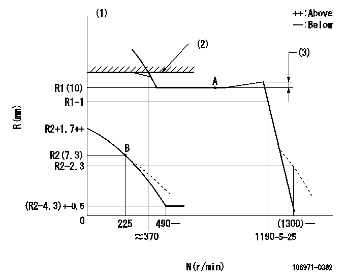
N:Pump speed
R:Rack position (mm)
(1)Damper spring setting: DL
(2)Rack limit using stop lever: RA
(3)Rack difference from N = N1
----------
DL=(R2-1)-0.2mm RA=(R1+0.6)+0.2mm N1=700r/min
----------
----------
DL=(R2-1)-0.2mm RA=(R1+0.6)+0.2mm N1=700r/min
----------
0000000901

F:Full load
I:Idle
(1)Stopper bolt setting
----------
----------
a=(14deg)+-3deg b=14deg+-5deg
----------
----------
a=(14deg)+-3deg b=14deg+-5deg
Stop lever angle
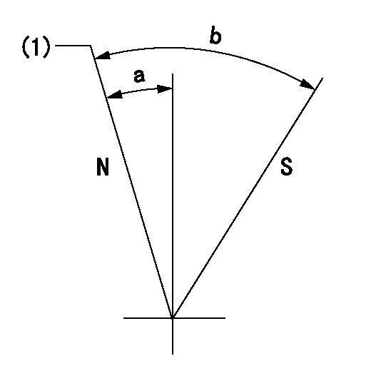
N:Pump normal
S:Stop the pump.
(1)Rack position = aa
----------
aa=(R1+0.6)+0.2mm
----------
a=(12deg)+-5deg b=(31deg)+-5deg
----------
aa=(R1+0.6)+0.2mm
----------
a=(12deg)+-5deg b=(31deg)+-5deg
Timing setting

(1)Pump vertical direction
(2)Position of the coupling's key groove at the start of injection for the No. 10 cylinder.
(3)-
(4)-
----------
----------
a=(90deg)
----------
----------
a=(90deg)
Information:
PARTS NEEDED
Qty
Part Number Description
6 1R6573 GASKET
1 2941706 GASKET
6 2941788 SEAL
1 2941790 PIPE
1 2941791 PIPE
1 2941792 PIPE
1 2941793 PIPE
1 2941794 PIPE
1 2941795 PIPE
6 2941803 SEAL-O-RING
6 3264756 INJECTOR GP-F -G
1 3280972 SOFTWARE GP-ELEK
In order to allow equitable parts availability to all participating dealers, please limit your initial parts order to not exceed 2% of dealership population. This is an initial order recommendation only, and the ultimate responsibility for ordering the total number of parts needed to satisfy the program lies with the dealer.
ACTION REQUIRED
If your engine is experiencing a lack of power and/or black smoke emissions, complete the following actions:
- Replace the six fuel injectors at the time of repair. Replace the existing unit injectors with the new 326-4756 Fuel Injector Groups. Refer to KENR8106, Disassembly and Assembly, for removal/install procedure of the fuel injector groups.
- Flash the new engine 328-0972 Software Group. The new engine software will change the engine power and therefore it is needed to request a Factory Password before flashing.
SERVICE CLAIM ALLOWANCES
Product smu/age whichever comes first Caterpillar Dealer Suggested Customer Suggested
Parts % Labor Hrs% Parts % Labor Hrs% Parts % Labor Hrs%
0-4000 hrs,
0-60 mo 100.0% 100.0% 0.0% 0.0% 0.0% 0.0%
4001-6000 hrs,
61-90 mo 33.0% 50.0% 0.0% 0.0% 50.0% 50.0%
This is a 4.0-hour job
PARTS DISPOSITION
Handle the parts in accordance with your Warranty Bulletin on warranty parts handling.
Have questions with 106971-0382?
Group cross 106971-0382 ZEXEL
Nissan-Diesel
Nissan-Diesel
Nissan-Diesel
Nissan-Diesel
106971-0382
9 400 618 624
1670097079
INJECTION-PUMP ASSEMBLY
RE10
RE10