Information injection-pump assembly
ZEXEL
106971-0371
1069710371

Rating:
Service parts 106971-0371 INJECTION-PUMP ASSEMBLY:
1.
_
5.
AUTOM. ADVANCE MECHANIS
7.
COUPLING PLATE
8.
_
9.
_
11.
Nozzle and Holder
1660097019
12.
Open Pre:MPa(Kqf/cm2)
19.6(200)

15.
NOZZLE SET
Include in #1:
106971-0371
as INJECTION-PUMP ASSEMBLY
Cross reference number
ZEXEL
106971-0371
1069710371
Zexel num
Bosch num
Firm num
Name
106971-0371
INJECTION-PUMP ASSEMBLY
Calibration Data:
Adjustment conditions
Test oil
1404 Test oil ISO4113 or {SAEJ967d}
1404 Test oil ISO4113 or {SAEJ967d}
Test oil temperature
degC
40
40
45
Nozzle and nozzle holder
105780-8140
Bosch type code
EF8511/9A
Nozzle
105780-0000
Bosch type code
DN12SD12T
Nozzle holder
105780-2080
Bosch type code
EF8511/9
Opening pressure
MPa
17.2
Opening pressure
kgf/cm2
175
Injection pipe
Outer diameter - inner diameter - length (mm) mm 8-3-600
Outer diameter - inner diameter - length (mm) mm 8-3-600
Overflow valve opening pressure
kPa
157
123
191
Overflow valve opening pressure
kgf/cm2
1.6
1.25
1.95
Tester oil delivery pressure
kPa
157
157
157
Tester oil delivery pressure
kgf/cm2
1.6
1.6
1.6
Direction of rotation (viewed from drive side)
Right R
Right R
Injection timing adjustment
Direction of rotation (viewed from drive side)
Right R
Right R
Injection order
10-9-4-3
-6-5-8-7
-2-1
Pre-stroke
mm
3.65
3.6
3.7
Beginning of injection position
Governor side NO.1
Governor side NO.1
Difference between angles 1
Cal 10-9 deg. 45 44.5 45.5
Cal 10-9 deg. 45 44.5 45.5
Difference between angles 2
Cal 10-4 deg. 72 71.5 72.5
Cal 10-4 deg. 72 71.5 72.5
Difference between angles 3
Cal 10-3 deg. 117 116.5 117.5
Cal 10-3 deg. 117 116.5 117.5
Difference between angles 4
Cal 10-6 deg. 144 143.5 144.5
Cal 10-6 deg. 144 143.5 144.5
Difference between angles 5
Cal 10-5 deg. 189 188.5 189.5
Cal 10-5 deg. 189 188.5 189.5
Difference between angles 6
Cal 10-8 deg. 216 215.5 216.5
Cal 10-8 deg. 216 215.5 216.5
Difference between angles 7
Cal 10-7 deg. 261 260.5 261.5
Cal 10-7 deg. 261 260.5 261.5
Difference between angles 8
Cal 10-2 deg. 288 287.5 288.5
Cal 10-2 deg. 288 287.5 288.5
Difference between angles 9
Cal 10-1 deg. 333 332.5 333.5
Cal 10-1 deg. 333 332.5 333.5
Injection quantity adjustment
Adjusting point
A
Rack position
10
Pump speed
r/min
700
700
700
Average injection quantity
mm3/st.
105.2
104.2
106.2
Max. variation between cylinders
%
0
-4
4
Basic
*
Fixing the lever
*
Injection quantity adjustment_02
Adjusting point
B
Rack position
6.3+-0.5
Pump speed
r/min
250
250
250
Average injection quantity
mm3/st.
12.9
10.9
14.9
Max. variation between cylinders
%
0
-10
10
Fixing the rack
*
Timer adjustment
Pump speed
r/min
800--
Advance angle
deg.
0
0
0
Remarks
Start
Start
Timer adjustment_02
Pump speed
r/min
750
Advance angle
deg.
0.5
Timer adjustment_03
Pump speed
r/min
950
Advance angle
deg.
2.2
1.7
2.7
Timer adjustment_04
Pump speed
r/min
1150
Advance angle
deg.
5.5
5
6
Remarks
Finish
Finish
Test data Ex:
Governor adjustment
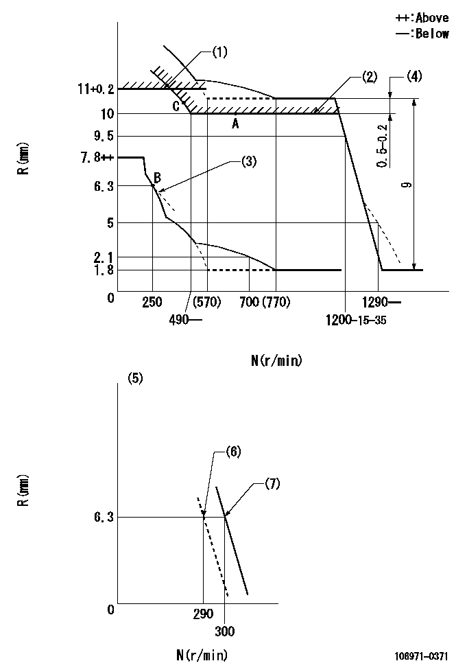
N:Pump speed
R:Rack position (mm)
(1)Rack limit using stop lever (at N = N1 or less).
(2)Excess fuel setting for starting
(3)Damper spring setting: DL
(4)At pump speed N2
(5)Variable speed specification: idling adjustment
(6)Main spring setting
(7)Set idle sub-spring
----------
N1=100r/min DL=6.3-0.2mm N2=1100r/min
----------
----------
N1=100r/min DL=6.3-0.2mm N2=1100r/min
----------
Speed control lever angle

F:Full speed
I:Idle
(1)Stopper bolt setting
----------
----------
a=(10deg)+-5deg b=(22deg)+-5deg
----------
----------
a=(10deg)+-5deg b=(22deg)+-5deg
0000000901
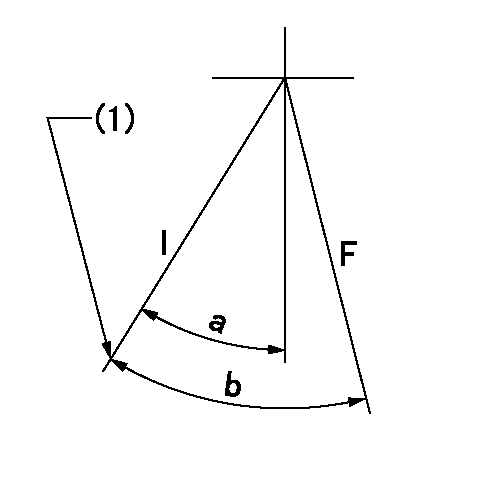
F:Full load
I:Idle
(1)Stopper bolt setting
----------
----------
a=24.5deg+-5deg b=31deg+-3deg
----------
----------
a=24.5deg+-5deg b=31deg+-3deg
Stop lever angle
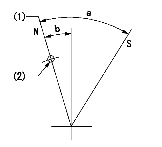
N:Pump normal
S:Stop the pump.
(1)Rack position = aa
(2)Use the hole at R = bb
----------
aa=11+0.2mm bb=32mm
----------
a=28.5deg+-5deg b=3deg+-5deg
----------
aa=11+0.2mm bb=32mm
----------
a=28.5deg+-5deg b=3deg+-5deg
Timing setting

(1)Pump vertical direction
(2)Position of the coupling's key groove at the start of injection for the No. 10 cylinder.
(3)-
(4)-
----------
----------
a=(90deg)
----------
----------
a=(90deg)
Information:
REM07-15
Reman
July 2007APPEARANCE CHANGE TO REMAN ELECTRONIC INJECTORS EI400, EI550 CLASSIC, BRIDGE, EI800 AND INJECTORS WITH ACERT? TECHNOLOGY EI500 AND EI550
Announcement
The Caterpillar Remanufactured Products Group announces an appearance change on selected Cat Reman electronic injectors EI400, EI550 Classic, Bridge, EI800 and injectors with ACERT? technology EI500 and EI550 effective 01/26/07. In order to improve the salvage of injectors? components, Cat Reman is introducing the reuse of solenoid with steel ring around the stator on the above mentioned electronic unit injectors.
Therefore, this will change the appearance of the injectors having stators with the steel ring around the solenoid and without it. However, this change will not alter fit or performance in any way. Please refer to the pictures and table below for more detail.
Part Numbers Impacted
The table below lists part numbers impacted by this appearance change.
Features And Benefits
Cat? Remanufactured Engine Components offer excellent value to customers. Customers who want fast repair turn-around, superior quality and reliability, and lower repair costs will benefit from the use of these Remanufactured Engine Components. Cat Remanufactured Engine Components provide immediate, off-the-shelf availability at a fraction of the new price.
Core Acceptance
Core Acceptance Criteria for Caterpillar Remanufactured Engine Components is simple, visual, and requires no special tools. Consult your Core Acceptance Guide for complete details.
Warranty
Please consult the appropriate warranty statement for your area.
Core Management
Please refer to the Caterpillar Core Management Information System (CMIS 2) Parts Information application describing all reman part/CAF and related information. Also refer to other CMIS 2 inquiry applications such as Customer Profiles, Inspection Reason Codes, Inspection Line Inquiry, Add Charge Information, Entitlement Activity, Entitlement Inquiry, CCR Inquiry, CCR Entry, Shipment Processing; Process Packaging Grief; and Reporting to properly manage core returns and monitor inspection performance. This information will be available to all dealers worldwide after your CMIS 2 conversion date. In the meantime, please continue to use the current CMIS Entitlement Parts Inquiry Screen describing the list of parts in a Core Acceptability Family (CAF) and related part number detail.
For the latest updates of Reman Policies and Core Management (SELD0122), Core Management Systems & Operations Procedures (SELD0040), and Shipping Instructions (SELD0039), go to the Reman Dealer website https://reman.cat.com
If you have any questions regarding core return processing, feel free to call Corinth toll free at (800) 537-2928. For assistance with technical questions, call the Peoria Reman Technical Help Line also toll free at (888) 88-REMAN or use our E-mail address--Reman_Help.
PELJ0791 CATERPILLAR? ?2007 Caterpillar
Have questions with 106971-0371?
Group cross 106971-0371 ZEXEL
Nissan-Diesel
Nissan-Diesel
106971-0371
INJECTION-PUMP ASSEMBLY