Information injection-pump assembly
ZEXEL
106971-0261
1069710261
Rating:
Service parts 106971-0261 INJECTION-PUMP ASSEMBLY:
1.
_
7.
COUPLING PLATE
8.
_
9.
_
11.
Nozzle and Holder
12.
Open Pre:MPa(Kqf/cm2)
19.6(200)

15.
NOZZLE SET
Include in #1:
106971-0261
as INJECTION-PUMP ASSEMBLY
Cross reference number
ZEXEL
106971-0261
1069710261
Zexel num
Bosch num
Firm num
Name
106971-0261
INJECTION-PUMP ASSEMBLY
Calibration Data:
Adjustment conditions
Test oil
1404 Test oil ISO4113 or {SAEJ967d}
1404 Test oil ISO4113 or {SAEJ967d}
Test oil temperature
degC
40
40
45
Nozzle and nozzle holder
105780-8140
Bosch type code
EF8511/9A
Nozzle
105780-0000
Bosch type code
DN12SD12T
Nozzle holder
105780-2080
Bosch type code
EF8511/9
Opening pressure
MPa
17.2
Opening pressure
kgf/cm2
175
Injection pipe
Outer diameter - inner diameter - length (mm) mm 8-3-600
Outer diameter - inner diameter - length (mm) mm 8-3-600
Overflow valve
132424-0620
Overflow valve opening pressure
kPa
157
123
191
Overflow valve opening pressure
kgf/cm2
1.6
1.25
1.95
Tester oil delivery pressure
kPa
157
157
157
Tester oil delivery pressure
kgf/cm2
1.6
1.6
1.6
Direction of rotation (viewed from drive side)
Right R
Right R
Injection timing adjustment
Direction of rotation (viewed from drive side)
Right R
Right R
Injection order
10-9-4-3
-6-5-8-7
-2-1
Pre-stroke
mm
3.65
3.6
3.7
Beginning of injection position
Governor side NO.1
Governor side NO.1
Difference between angles 1
Cal 10-9 deg. 45 44.5 45.5
Cal 10-9 deg. 45 44.5 45.5
Difference between angles 2
Cal 10-4 deg. 72 71.5 72.5
Cal 10-4 deg. 72 71.5 72.5
Difference between angles 3
Cal 10-3 deg. 117 116.5 117.5
Cal 10-3 deg. 117 116.5 117.5
Difference between angles 4
Cal 10-6 deg. 144 143.5 144.5
Cal 10-6 deg. 144 143.5 144.5
Difference between angles 5
Cal 10-5 deg. 189 188.5 189.5
Cal 10-5 deg. 189 188.5 189.5
Difference between angles 6
Cal 10-8 deg. 216 215.5 216.5
Cal 10-8 deg. 216 215.5 216.5
Difference between angles 7
Cal 10-7 deg. 261 260.5 261.5
Cal 10-7 deg. 261 260.5 261.5
Difference between angles 8
Cal 10-2 deg. 288 287.5 288.5
Cal 10-2 deg. 288 287.5 288.5
Difference between angles 9
Cal 10-1 deg. 333 332.5 333.5
Cal 10-1 deg. 333 332.5 333.5
Injection quantity adjustment
Adjusting point
A
Rack position
10.3
Pump speed
r/min
700
700
700
Average injection quantity
mm3/st.
107.2
106.2
108.2
Max. variation between cylinders
%
0
-4
4
Basic
*
Fixing the lever
*
Injection quantity adjustment_02
Adjusting point
B
Rack position
5.7+-0.5
Pump speed
r/min
250
250
250
Average injection quantity
mm3/st.
11.9
9.9
13.9
Max. variation between cylinders
%
0
-10
10
Fixing the rack
*
Timer adjustment
Pump speed
r/min
600--
Advance angle
deg.
0
0
0
Remarks
Start
Start
Timer adjustment_02
Pump speed
r/min
550
Advance angle
deg.
0.5
Timer adjustment_03
Pump speed
r/min
700
Advance angle
deg.
1
0.5
1.5
Timer adjustment_04
Pump speed
r/min
1150
Advance angle
deg.
5.5
5
6
Remarks
Finish
Finish
Test data Ex:
Governor adjustment
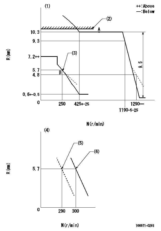
N:Pump speed
R:Rack position (mm)
(1)Beginning of damper spring operation: DL
(2)Rack limit using the stop lever: R1
(3)Damper spring setting
(4)Variable speed specification: idling adjustment
(5)Main spring setting
(6)Set idle sub-spring
----------
DL=5.7-0.2mm R1=10.6+0.2mm
----------
----------
DL=5.7-0.2mm R1=10.6+0.2mm
----------
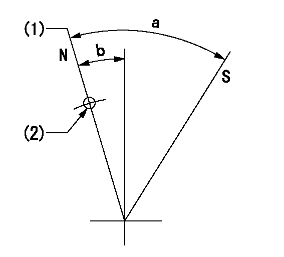
Speed control lever angle
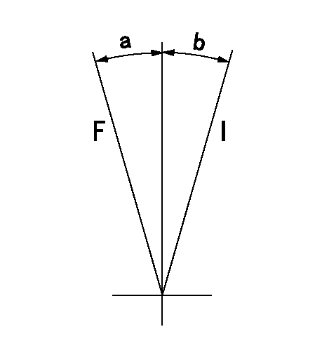
F:Full speed
I:Idle
----------
----------
a=9.5deg+-5deg b=10deg+-5deg
----------
----------
a=9.5deg+-5deg b=10deg+-5deg
0000000901
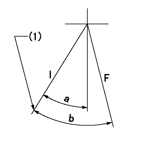
F:Full load
I:Idle
(1)Stopper bolt setting
----------
----------
a=24.5deg+-5deg b=33deg+-3deg
----------
----------
a=24.5deg+-5deg b=33deg+-3deg
Stop lever angle
N:Pump normal
S:Stop the pump.
(1)Rack position = aa
(2)Use the hole at R = bb
----------
aa=10.6+0.2mm bb=32mm
----------
a=27.5deg+-5deg b=2deg+-5deg
----------
aa=10.6+0.2mm bb=32mm
----------
a=27.5deg+-5deg b=2deg+-5deg
Timing setting

(1)Pump vertical direction
(2)Position of the coupling's key groove at the start of injection for the No. 10 cylinder.
(3)-
(4)-
----------
----------
a=(90deg)
----------
----------
a=(90deg)
Information:
Features and Benefits
Reman short blocks expand the repair options available. When used with other
remanufactured products and reusable components from the core engine, short blocks help
lower dealer repair/rebuild cost and shorten turnaround time.
The 3500B short block is a fully assembled cylinder block with sequence valves, crankshaft,
cylinder pack groups, piston jets, camshaft bearings, and lifting eyes.
The short block does not include camshaft, cam access covers, or block side covers. The
short block may contain a remanufactured cylinder block, crankshaft, connecting rods, and
pistons. The cylinder liners, piston rings, camshaft bearings, and crankshaft bearings are
100% new components. The remanufactured components are remanufactured to factory
specifications using factory precision machine tools and proven processes.
Core Acceptance
Short blocks from 3500B diesel series machine and commercial engines that were built with
101-0829 Piston ? Rod Gp. are acceptable as core. Reference SELD0026 for the latest Short
Block Core Acceptance Criteria.
Core Management
Please refer to the Caterpillar Core Management Information System (CMIS 2) Parts
Information application describing all reman part/CAF and related information. Also refer to
other CMIS 2 inquiry applications such as Customer Profiles, Inspection Reason Codes,
Inspection Line Inquiry, Add Charge Information, Entitlement Activity, Entitlement Inquiry,
CCR Inquiry, CCR Entry, Shipment Processing; Process Packaging Grief; and Reporting to
properly manage core returns and monitor inspection performance. This information will be
available to all dealers worldwide after your CMIS 2 conversion date. In the meantime,
please continue to use the current CMIS Entitlement Parts Inquiry Screen describing the list
of parts in a Core Acceptability Family (CAF) and related part number detail.
For the latest updates of Reman Policies and Core Management (SELD0122), Core
Management Systems & Operations Procedures (SELD0040), and Shipping Instructions
(SELD0039), go to the Reman website and click on Procedures and Policies (listed under
Reman Program Information).
Please note that 3500B short block core will be shipped to Lafayette address:
Caterpillar Inc.
3701 State Road 26 East
Lafayette, Indiana, 47905
U.S.A.
See "SHIPPING INSTRUCTIONS" (SELD0039) for more information.
If you have any questions regarding core return processing, feel free to call Corinth toll free
at (800) 537-2928. For assistance with technical questions, call the Peoria Reman
Customer Satisfaction Hot Line also toll free at (888) 88-REMAN or use our E-mail
address--Reman_Help.
James E. Reynolds
Dept: 3500 Reman Engines
Location: 88-B21L
Phone: 765-448-2295
Fax: 765-448-5897
Have questions with 106971-0261?
Group cross 106971-0261 ZEXEL
Nissan-Diesel
Nissan-Diesel
Nissan-Diesel
Nissan-Diesel
106971-0261
INJECTION-PUMP ASSEMBLY