Information injection-pump assembly
ZEXEL
106971-0221
1069710221
NISSAN-DIESEL
1679097014
1679097014
Rating:
Service parts 106971-0221 INJECTION-PUMP ASSEMBLY:
1.
_
6.
COUPLING PLATE
7.
COUPLING PLATE
8.
_
9.
_
11.
Nozzle and Holder
12.
Open Pre:MPa(Kqf/cm2)
22.6(230)
15.
NOZZLE SET
Include in #1:
106971-0221
as INJECTION-PUMP ASSEMBLY
Cross reference number
ZEXEL
106971-0221
1069710221
NISSAN-DIESEL
1679097014
1679097014
Zexel num
Bosch num
Firm num
Name
106971-0221
1679097014 NISSAN-DIESEL
INJECTION-PUMP ASSEMBLY
RD10T06 * K
RD10T06 * K
Calibration Data:
Adjustment conditions
Test oil
1404 Test oil ISO4113 or {SAEJ967d}
1404 Test oil ISO4113 or {SAEJ967d}
Test oil temperature
degC
40
40
45
Nozzle and nozzle holder
105780-8140
Bosch type code
EF8511/9A
Nozzle
105780-0000
Bosch type code
DN12SD12T
Nozzle holder
105780-2080
Bosch type code
EF8511/9
Opening pressure
MPa
17.2
Opening pressure
kgf/cm2
175
Injection pipe
Outer diameter - inner diameter - length (mm) mm 8-3-600
Outer diameter - inner diameter - length (mm) mm 8-3-600
Overflow valve
132424-0620
Overflow valve opening pressure
kPa
157
123
191
Overflow valve opening pressure
kgf/cm2
1.6
1.25
1.95
Tester oil delivery pressure
kPa
157
157
157
Tester oil delivery pressure
kgf/cm2
1.6
1.6
1.6
Direction of rotation (viewed from drive side)
Right R
Right R
Injection timing adjustment
Direction of rotation (viewed from drive side)
Right R
Right R
Injection order
10-9-4-3
-6-5-8-7
-2-1
Pre-stroke
mm
3.65
3.6
3.7
Beginning of injection position
Governor side NO.1
Governor side NO.1
Difference between angles 1
Cal 10-9 deg. 45 44.5 45.5
Cal 10-9 deg. 45 44.5 45.5
Difference between angles 2
Cal 10-4 deg. 72 71.5 72.5
Cal 10-4 deg. 72 71.5 72.5
Difference between angles 3
Cal 10-3 deg. 117 116.5 117.5
Cal 10-3 deg. 117 116.5 117.5
Difference between angles 4
Cal 10-6 deg. 144 143.5 144.5
Cal 10-6 deg. 144 143.5 144.5
Difference between angles 5
Cal 10-5 deg. 189 188.5 189.5
Cal 10-5 deg. 189 188.5 189.5
Difference between angles 6
Cal 10-8 deg. 216 215.5 216.5
Cal 10-8 deg. 216 215.5 216.5
Difference between angles 7
Cal 10-7 deg. 261 260.5 261.5
Cal 10-7 deg. 261 260.5 261.5
Difference between angles 8
Cal 10-2 deg. 288 287.5 288.5
Cal 10-2 deg. 288 287.5 288.5
Difference between angles 9
Cal 10-1 deg. 333 332.5 333.5
Cal 10-1 deg. 333 332.5 333.5
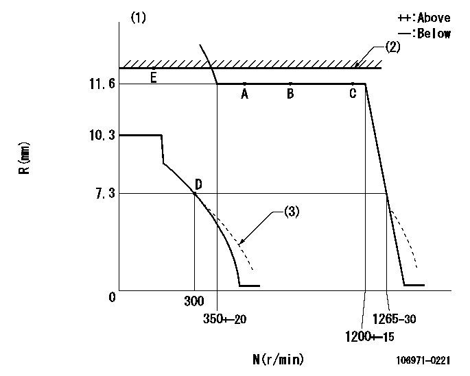
Injection quantity adjustment
Adjusting point
A
Rack position
11.6
Pump speed
r/min
500
500
500
Average injection quantity
mm3/st.
128.9
122.9
134.9
Max. variation between cylinders
%
0
-4
4
Fixing the lever
*
Injection quantity adjustment_02
Adjusting point
B
Rack position
11.6
Pump speed
r/min
750
750
750
Average injection quantity
mm3/st.
131.5
125.5
137.5
Max. variation between cylinders
%
0
-4
4
Fixing the lever
*
Injection quantity adjustment_03
Adjusting point
C
Rack position
11.6
Pump speed
r/min
1150
1150
1150
Average injection quantity
mm3/st.
125
123
127
Max. variation between cylinders
%
0
-4
4
Basic
*
Fixing the lever
*
Injection quantity adjustment_04
Adjusting point
D
Rack position
7.3+-0.5
Pump speed
r/min
300
300
300
Average injection quantity
mm3/st.
17.8
15.8
19.8
Max. variation between cylinders
%
0
-10
10
Fixing the rack
*
Timer adjustment
Pump speed
r/min
300+100
Advance angle
deg.
0
0
0
Remarks
Start
Start
Timer adjustment_02
Pump speed
r/min
600
Advance angle
deg.
1.7
1.2
2.2
Timer adjustment_03
Pump speed
r/min
900
Advance angle
deg.
3.4
2.9
3.9
Timer adjustment_04
Pump speed
r/min
1250+50
Advance angle
deg.
5.5
5
6
Remarks
Finish
Finish
Test data Ex:
Governor adjustment
N:Pump speed
R:Rack position (mm)
(1)Target notch: K
(2)RACK LIMIT: RAL
(3)Damper spring setting: DL
----------
K=9 RAL=12.4+-0.1mm DL=6.8-0.2mm
----------
----------
K=9 RAL=12.4+-0.1mm DL=6.8-0.2mm
----------
Speed control lever angle

F:Full speed
I:Idle
S:Stop
----------
----------
a=9deg+-5deg b=32deg+-3deg c=30deg+-5deg
----------
----------
a=9deg+-5deg b=32deg+-3deg c=30deg+-5deg
Stop lever angle
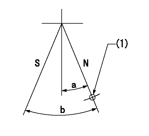
N:Pump normal
S:Stop the pump.
(1)Use the hole at R = aa
----------
aa=55mm
----------
a=27deg+-5deg b=53deg+-5deg
----------
aa=55mm
----------
a=27deg+-5deg b=53deg+-5deg
0000001501 GOV FULL LOAD ADJUSTMENT
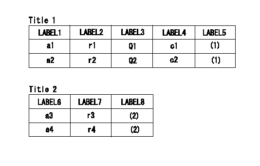
Title1:Full load stopper adjustment
Title2:Governor set speed
LABEL1:Distinguishing
LABEL2:Pump speed (r/min)
LABEL3:Ave. injection quantity (mm3/st)
LABEL4:Max. var. bet. cyl.
LABEL5:Remarks
LABEL6:Distinguishing
LABEL7:Governor set speed (r/min)
LABEL8:Remarks
(1)Adjustment conditions are the same as those for measuring injection quantity.
(2)-
----------
----------
a1=M a2=F r1=1150r/min r2=1150r/min Q1=125+-2mm3/st Q2=115+-2mm3/st c1=+-4% c2=+-4% a3=M a4=F r3=1185r/min r4=1150r/min
----------
----------
a1=M a2=F r1=1150r/min r2=1150r/min Q1=125+-2mm3/st Q2=115+-2mm3/st c1=+-4% c2=+-4% a3=M a4=F r3=1185r/min r4=1150r/min
Information:
Operations that may cause product damage are identified by notice labels in this publication.
Introduction
This Tool Operating Manual contains two filter installation procedures. This first procedure is for installing a primary filter system. This is a coarse filter and will protect the transfer pump from contamination in the oil. The second procedure outlines installing a secondary filter which is designed to protect injection pumps from contaminated oil. Fuel injection pumps used on the 3208 Engine are one example of a fuel injection pump that requires the secondary filter installation.It will be the dealer choice as to which optional filter is installed on the test stand. Determine what type of filtering will be required most often, and install the appropriate type of filtering system. These filters can only be added to the 15 horsepower test stands.Secondary Filter
Nomenclature
Illustration 1. Nomenclature for Secondary Filter Installation. Refer to Chart A for item identification. Fabricated Parts
All the parts required for this installation can be ordered from Caterpillar Parts Distribution, except bracket (1). This must be manufactured by the bench owner, using the dimensions provided below.This bracket can be made from common SAE1018 steel. Weld the two pieces together.
Illustration 2. Filter Mounting Bracket. Refer to Chart B for dimensions. Installation
Assemble the Fuel Filter
1. Install 053-0088 Fitting (17) with 3J-1907 Seal (18) into the inlet port (left side) of the filter base. (This converts a number 6 STOP port to NPT). Install 5P-4455 Fitting (19) into fitting (17).2. Install 2R-6806 Fitting (15) with 3J-1907 Seal (16) into the outlet port (right side) of the filter base.3. Install 6N-4414 Cover (7) onto the filter base using 1P-0436 Gasket (8), 4B-3388/6V-2317 (9), and OS-1616/6V-8490 Bolt (10).4. Install 9S-4182 Plug (5) with 6V-5084 O-ring Seal (6) into the top of the filter base.5. Install the filter base assembly onto filter bracket (1),
Have questions with 106971-0221?
Group cross 106971-0221 ZEXEL
Nissan-Diesel
Nissan-Diesel
106971-0221
1679097014
INJECTION-PUMP ASSEMBLY
RD10T06
RD10T06