Information injection-pump assembly
BOSCH
9 400 618 617
9400618617
ZEXEL
106971-0213
1069710213
NISSAN-DIESEL
1679097062
1679097062

Rating:
Service parts 106971-0213 INJECTION-PUMP ASSEMBLY:
1.
_
6.
COUPLING PLATE
7.
COUPLING PLATE
8.
_
9.
_
11.
Nozzle and Holder
16600-97005
12.
Open Pre:MPa(Kqf/cm2)
22.6{230}
15.
NOZZLE SET
Include in #1:
106971-0213
as INJECTION-PUMP ASSEMBLY
Cross reference number
BOSCH
9 400 618 617
9400618617
ZEXEL
106971-0213
1069710213
NISSAN-DIESEL
1679097062
1679097062
Zexel num
Bosch num
Firm num
Name
106971-0213
9 400 618 617
1679097062 NISSAN-DIESEL
INJECTION-PUMP ASSEMBLY
RD10T04 K 14CE INJECTION PUMP ASSY PE10P PE
RD10T04 K 14CE INJECTION PUMP ASSY PE10P PE
Calibration Data:
Adjustment conditions
Test oil
1404 Test oil ISO4113 or {SAEJ967d}
1404 Test oil ISO4113 or {SAEJ967d}
Test oil temperature
degC
40
40
45
Nozzle and nozzle holder
105780-8140
Bosch type code
EF8511/9A
Nozzle
105780-0000
Bosch type code
DN12SD12T
Nozzle holder
105780-2080
Bosch type code
EF8511/9
Opening pressure
MPa
17.2
Opening pressure
kgf/cm2
175
Injection pipe
Outer diameter - inner diameter - length (mm) mm 8-3-600
Outer diameter - inner diameter - length (mm) mm 8-3-600
Overflow valve
132424-0620
Overflow valve opening pressure
kPa
157
123
191
Overflow valve opening pressure
kgf/cm2
1.6
1.25
1.95
Tester oil delivery pressure
kPa
157
157
157
Tester oil delivery pressure
kgf/cm2
1.6
1.6
1.6
Direction of rotation (viewed from drive side)
Right R
Right R
Injection timing adjustment
Direction of rotation (viewed from drive side)
Right R
Right R
Injection order
10-9-4-3
-6-5-8-7
-2-1
Pre-stroke
mm
3.65
3.6
3.7
Beginning of injection position
Governor side NO.1
Governor side NO.1
Difference between angles 1
Cal 10-9 deg. 45 44.5 45.5
Cal 10-9 deg. 45 44.5 45.5
Difference between angles 2
Cal 10-4 deg. 72 71.5 72.5
Cal 10-4 deg. 72 71.5 72.5
Difference between angles 3
Cal 10-3 deg. 117 116.5 117.5
Cal 10-3 deg. 117 116.5 117.5
Difference between angles 4
Cal 10-6 deg. 144 143.5 144.5
Cal 10-6 deg. 144 143.5 144.5
Difference between angles 5
Cal 10-5 deg. 189 188.5 189.5
Cal 10-5 deg. 189 188.5 189.5
Difference between angles 6
Cal 10-8 deg. 216 215.5 216.5
Cal 10-8 deg. 216 215.5 216.5
Difference between angles 7
Cal 10-7 deg. 261 260.5 261.5
Cal 10-7 deg. 261 260.5 261.5
Difference between angles 8
Cal 10-2 deg. 288 287.5 288.5
Cal 10-2 deg. 288 287.5 288.5
Difference between angles 9
Cal 10-1 deg. 333 332.5 333.5
Cal 10-1 deg. 333 332.5 333.5
Injection quantity adjustment
Adjusting point
A
Rack position
12.1
Pump speed
r/min
750
750
750
Average injection quantity
mm3/st.
138.5
137.5
139.5
Max. variation between cylinders
%
0
-2.5
2.5
Basic
*
Fixing the lever
*
Boost pressure
kPa
38
38
Boost pressure
mmHg
285
285
Injection quantity adjustment_02
Adjusting point
B
Rack position
10.8
Pump speed
r/min
500
500
500
Average injection quantity
mm3/st.
109.5
107.5
111.5
Max. variation between cylinders
%
0
-4
4
Fixing the lever
*
Boost pressure
kPa
0
0
0
Boost pressure
mmHg
0
0
0
Injection quantity adjustment_03
Adjusting point
C
Rack position
7.6+-0.5
Pump speed
r/min
300
300
300
Average injection quantity
mm3/st.
13
11.9
14.1
Max. variation between cylinders
%
0
-15
15
Fixing the rack
*
Boost pressure
kPa
0
0
0
Boost pressure
mmHg
0
0
0
Boost compensator adjustment
Pump speed
r/min
500
500
500
Rack position
10.8
Boost pressure
kPa
16
9.3
22.7
Boost pressure
mmHg
120
70
170
Boost compensator adjustment_02
Pump speed
r/min
500
500
500
Rack position
12.1
Boost pressure
kPa
30
28.7
31.3
Boost pressure
mmHg
225
215
235
Timer adjustment
Pump speed
r/min
300+100
Advance angle
deg.
0
0
0
Remarks
Start
Start
Timer adjustment_02
Pump speed
r/min
600
Advance angle
deg.
1.7
1.2
2.2
Timer adjustment_03
Pump speed
r/min
900
Advance angle
deg.
3.4
2.9
3.9
Timer adjustment_04
Pump speed
r/min
1250+50
Advance angle
deg.
5.5
5
6
Remarks
Finish
Finish
Test data Ex:
Governor adjustment
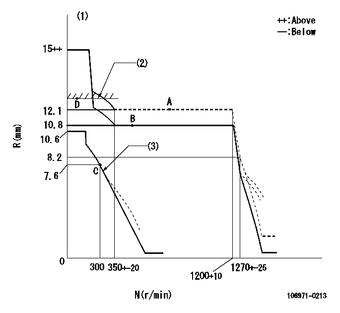
N:Pump speed
R:Rack position (mm)
(1)Target notch: K
(2)RACK LIMIT: RAL
(3)Damper spring setting: DL
----------
K=10 RAL=12.8+-0.1mm DL=7.6-0.2mm
----------
----------
K=10 RAL=12.8+-0.1mm DL=7.6-0.2mm
----------
Speed control lever angle

F:Full speed
I:Idle
S:Stop
----------
----------
a=13deg+-5deg b=32deg+-3deg c=30deg+-5deg
----------
----------
a=13deg+-5deg b=32deg+-3deg c=30deg+-5deg
Stop lever angle

N:Pump normal
S:Stop the pump.
----------
----------
a=16.5deg+-5deg b=50deg+-5deg
----------
----------
a=16.5deg+-5deg b=50deg+-5deg
0000001501 GOV FULL LOAD ADJUSTMENT
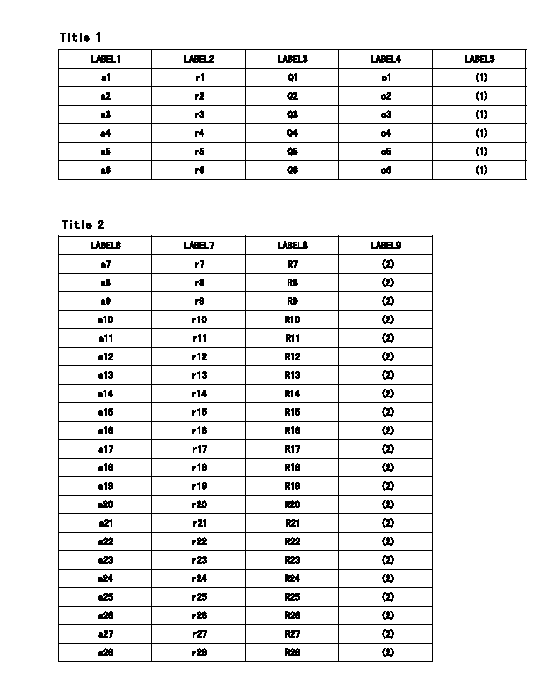
Title1:Full load stopper adjustment
Title2:Governor set speed
LABEL1:Distinguishing
LABEL2:Pump speed (r/min)
LABEL3:Ave. injection quantity (mm3/st)
LABEL4:Max. var. bet. cyl.
LABEL5:Remarks
LABEL6:Distinguishing
LABEL7:Governor set speed (r/min)
LABEL8:Maximum no-load speed (r/min)
LABEL9:Remarks
(1)Adjustment conditions are the same as those for measuring injection quantity.
(2)At high idle rack position L
----------
L=8.2mm
----------
a1=B a2=C a3=D a4=- a5=- a6=- r1=750r/min r2=700r/min r3=700r/min r4=- r5=- r6=- Q1=138.5+-1mm3/st Q2=126.5+-1mm3/st Q3=103+-1 mm3/st Q4=- Q5=- Q6=- c1=+-2.5% c2=+-2.5% c3=+-2.5% c4=- c5=- c6=- a7=24 a8=23 a9=22 a10=21 a11=20 a12=19 a13=18 a14=17 a15=16 a16=15 a17=14 a18=13 a19=- a20=- a21=- a22=- a23=- a24=- a25=- a26=- a27=- a28=- r7=1200r/min r8=1150r/min r9=1100r/min r10=1050r/min r11=1000r/min r12=950r/min r13=900r/min r14=850r/min r15=800r/min r16=750r/min r17=700r/min r18=650r/min r19=- r20=- r21=- r22=- r23=- r24=- r25=- r26=- r27=- r28=- R7=1290+-30r/min R8=1235+-28r/min R9=1180+-27r/min R10=1130+-26r/min R11=1075+-25r/min R12=1020+-23r/min R13=965+-22r/min R14=915+-22r/min R15=860+-20r/min R16=805+-18r/min R17=750+-17r/min R18=695+-16r/min R19=- R20=- R21=- R22=- R23=- R24=- R25=- R26=- R27=- R28=-
----------
L=8.2mm
----------
a1=B a2=C a3=D a4=- a5=- a6=- r1=750r/min r2=700r/min r3=700r/min r4=- r5=- r6=- Q1=138.5+-1mm3/st Q2=126.5+-1mm3/st Q3=103+-1 mm3/st Q4=- Q5=- Q6=- c1=+-2.5% c2=+-2.5% c3=+-2.5% c4=- c5=- c6=- a7=24 a8=23 a9=22 a10=21 a11=20 a12=19 a13=18 a14=17 a15=16 a16=15 a17=14 a18=13 a19=- a20=- a21=- a22=- a23=- a24=- a25=- a26=- a27=- a28=- r7=1200r/min r8=1150r/min r9=1100r/min r10=1050r/min r11=1000r/min r12=950r/min r13=900r/min r14=850r/min r15=800r/min r16=750r/min r17=700r/min r18=650r/min r19=- r20=- r21=- r22=- r23=- r24=- r25=- r26=- r27=- r28=- R7=1290+-30r/min R8=1235+-28r/min R9=1180+-27r/min R10=1130+-26r/min R11=1075+-25r/min R12=1020+-23r/min R13=965+-22r/min R14=915+-22r/min R15=860+-20r/min R16=805+-18r/min R17=750+-17r/min R18=695+-16r/min R19=- R20=- R21=- R22=- R23=- R24=- R25=- R26=- R27=- R28=-
Information:
Changing Filter Element
A 1U-9578 Repair Kit (Nozzle Tester) is available to maintain the tester. The repair kit contains a new filter along with seals, gaskets, and instructions on how to use the kit. Do not reuse seals and gaskets when changing the filter. Always use new seals and gaskets.Calibration Fluid
The calibration fluid should be changed every three months or after testing 50 nozzles. The fluid should also be changed whenever inaccurate test results are suspected.Inaccurate test results can be caused by fluid with improper specific gravity, viscosity, visible contamination, fluid that foams, or discolored fluid.The fluid should also be checked for the correct viscosity. It is a good practice to test new calibration fluid for the correct viscosity and specific gravity. Use a 9U-7840 Test Kit to check calibration fluid.
Do not refill the nozzle tester with test oil that has been pumped through a fuel injection nozzle. Nozzles contain residual amounts of diesel fuel that is pumped out when tested. The diesel fuel mixes with and contaminates the test oil. Using this diesel fuel test oil combination will damage the nozzle tester.
9U-7840 Test Kit For Checking Fluid Viscosity Calibration fluid will last longer if the nozzles are cleaned prior to testing. As the fluid in the tester becomes contaminated, the accuracy of the test results are decreased.Changing Calibration Fluid
1. Completely drain the reservoir and any fluid contained in the pump mechanism. Special care must be taken for the disposal of the calibration fluid. Recent regulations prohibit the dumping of oil; all oil must be properly disposed.2. Thoroughly clean the reservoir using an 8T-9011 Component Cleaner or equivalent and clean towels.3. Install a new 8T-5313 Filter Element (10 micron). A new filter element should be installed whenever the calibration fluid is changed (even if less than 3 months).4. Fill the reservoir with clean calibration fluid (refer to the chart for part numbers).Nozzle Tester Pressure Gauges
Pressure gauges in the nozzle tester should be checked for accuracy every 12 months or whenever inaccurate test results are suspected. Gauges should also be checked whenever a gauge is damaged or the needle does not return to zero. Record all data on the data sheets in the "Forms" section.1. Remove pressure gauge from the nozzle tester.2. Install gauge adapter from 5P-8558 Calibrating Group Pressure Gauge onto pressure gauge.3. Connect pressure to tester port.4. Use a 1U-5230 Hand Pump to apply pressure to the gauge. Increase the pressure to 25% of the pressure gauges capacity.5. Check the actual gauge pressure with the tester gauge reading. The two pressures should be within two percent of each other.6. Repeat Step 5 at 50, 75 and 100 percent increments. Each increment should be within two percent of the tester gauge reading.7. If the pressure is not within two percent, the pressure gauge should be replaced.Check Tester For Leakage
Before testing any nozzle, check the tester for obvious external leakage. Leakage in the tester will give inaccurate test results, causing good nozzles to be rejected.Always check the tester for leakage
Have questions with 106971-0213?
Group cross 106971-0213 ZEXEL
Nissan-Diesel
Nissan-Diesel
106971-0213
9 400 618 617
1679097062
INJECTION-PUMP ASSEMBLY
RD10T04
RD10T04