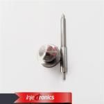
Information injection-pump assembly
BOSCH
F 019 Z10 653
f019z10653
ZEXEL
106961-6070
1069616070
ISUZU
1156027540
1156027540
Rating:
Service parts 106961-6070 INJECTION-PUMP ASSEMBLY:
1.
_
6.
COUPLING PLATE
7.
COUPLING PLATE
8.
_
9.
_
11.
Nozzle and Holder
12.
Open Pre:MPa(Kqf/cm2)
15.7(160)/22.1(225)
15.
NOZZLE SET
Include in #1:
106961-6070
as INJECTION-PUMP ASSEMBLY
Cross reference number
BOSCH
F 019 Z10 653
f019z10653
ZEXEL
106961-6070
1069616070
ISUZU
1156027540
1156027540
Zexel num
Bosch num
Firm num
Name
Calibration Data:
Adjustment conditions
Test oil
1404 Test oil ISO4113 or {SAEJ967d}
1404 Test oil ISO4113 or {SAEJ967d}
Test oil temperature
degC
40
40
45
Nozzle and nozzle holder
105780-8140
Bosch type code
EF8511/9A
Nozzle
105780-0000
Bosch type code
DN12SD12T
Nozzle holder
105780-2080
Bosch type code
EF8511/9
Opening pressure
MPa
17.2
Opening pressure
kgf/cm2
175
Injection pipe
Outer diameter - inner diameter - length (mm) mm 8-3-600
Outer diameter - inner diameter - length (mm) mm 8-3-600
Overflow valve (drive side)
134424-4320
Overflow valve opening pressure (drive side)
kPa
255
221
289
Overflow valve opening pressure (drive side)
kgf/cm2
2.6
2.25
2.95
Overflow valve (governor side)
134424-4320
Overflow valve opening pressure (governor side)
kPa
255
221
289
Overflow valve opening pressure (governor side)
kgf/cm2
2.6
2.25
2.95
Tester oil delivery pressure
kPa
157
157
157
Tester oil delivery pressure
kgf/cm2
1.6
1.6
1.6
Direction of rotation (viewed from drive side)
Right R
Right R
Injection timing adjustment
Direction of rotation (viewed from drive side)
Right R
Right R
Injection order
1-4-9-8-
5-2-11-1
0-3-6-7-
Pre-stroke
mm
4.4
4.37
4.43
Rack position
Point A R=A
Point A R=A
Beginning of injection position
Governor side NO.1
Governor side NO.1
Difference between angles 1
Cal 1-4 deg. 15 14.75 15.25
Cal 1-4 deg. 15 14.75 15.25
Difference between angles 2
Cal 1-9 deg. 60 59.75 60.25
Cal 1-9 deg. 60 59.75 60.25
Difference between angles 3
Cal 1-8 deg. 75 74.75 75.25
Cal 1-8 deg. 75 74.75 75.25
Difference between angles 4
Cal 1-5 deg. 120 119.75 120.25
Cal 1-5 deg. 120 119.75 120.25
Difference between angles 5
Cyl.1-2 deg. 135 134.75 135.25
Cyl.1-2 deg. 135 134.75 135.25
Difference between angles 6
Cal 1-11 deg. 180 179.75 180.25
Cal 1-11 deg. 180 179.75 180.25
Difference between angles 7
Cal 1-10 deg. 195 194.75 195.25
Cal 1-10 deg. 195 194.75 195.25
Difference between angles 8
Cal 1-3 deg. 240 239.75 240.25
Cal 1-3 deg. 240 239.75 240.25
Difference between angles 9
Cal 1-6 deg. 255 254.75 255.25
Cal 1-6 deg. 255 254.75 255.25
Difference between angles 10
Cal 1-7 deg. 300 299.75 300.25
Cal 1-7 deg. 300 299.75 300.25
Difference between angles 11
Cal 1-12 deg. 315 314.75 315.25
Cal 1-12 deg. 315 314.75 315.25
Injection quantity adjustment
Adjusting point
A
Rack position
8.3
Pump speed
r/min
800
800
800
Average injection quantity
mm3/st.
96.1
94.6
97.6
Max. variation between cylinders
%
0
-2
2
Basic
*
Fixing the lever
*
Injection quantity adjustment_02
Adjusting point
B
Rack position
8.6
Pump speed
r/min
500
500
500
Average injection quantity
mm3/st.
96.8
94.8
98.8
Fixing the lever
*
Injection quantity adjustment_03
Adjusting point
C
Rack position
7.9
Pump speed
r/min
1100
1100
1100
Average injection quantity
mm3/st.
101.1
99.1
103.1
Fixing the lever
*
Injection quantity adjustment_04
Adjusting point
D
Rack position
5.2+-0.5
Pump speed
r/min
225
225
225
Average injection quantity
mm3/st.
8.8
7.5
10.1
Max. variation between cylinders
%
0
-13
13
Fixing the rack
*
Timer adjustment
Pump speed
r/min
600--
Advance angle
deg.
0
0
0
Remarks
Start
Start
Timer adjustment_02
Pump speed
r/min
550
Advance angle
deg.
0.3
Timer adjustment_03
Pump speed
r/min
830+-30
Advance angle
deg.
2
1.5
2.5
Timer adjustment_04
Pump speed
r/min
-
Advance angle
deg.
2
1.5
2.5
Remarks
Measure the actual speed.
Measure the actual speed.
Timer adjustment_05
Pump speed
r/min
1100
Advance angle
deg.
5.5
5
6
Remarks
Finish
Finish
Test data Ex:
Governor adjustment
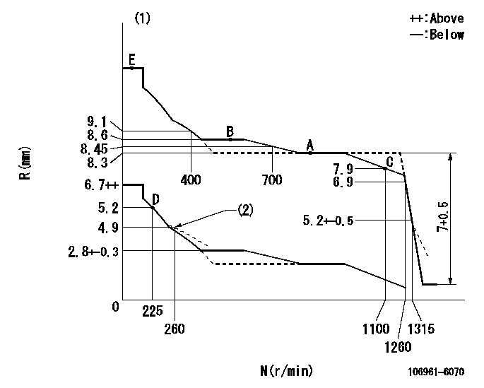
N:Pump speed
R:Rack position (mm)
(1)Tolerance for racks not indicated: +-0.05mm.
(2)Damper spring setting
----------
----------
----------
----------
Speed control lever angle

F:Full speed
----------
----------
a=7deg+-5deg
----------
----------
a=7deg+-5deg
0000000901
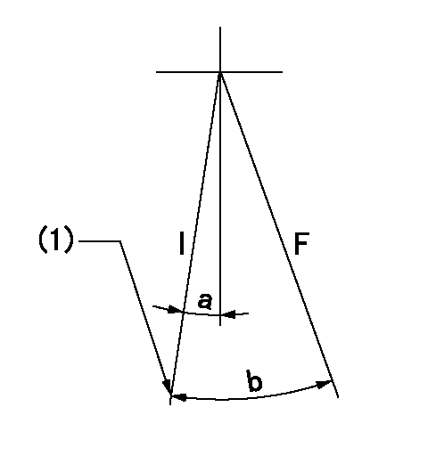
F:Full load
I:Idle
(1)Stopper bolt setting
----------
----------
a=10deg+-5deg b=31deg+-3deg
----------
----------
a=10deg+-5deg b=31deg+-3deg
Stop lever angle
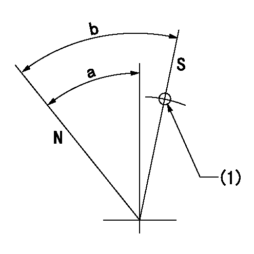
N:Pump normal
S:Stop the pump.
(1)Use the hole at R = aa
----------
aa=25mm
----------
a=51deg+-5deg b=64deg+-5deg
----------
aa=25mm
----------
a=51deg+-5deg b=64deg+-5deg
Timing setting
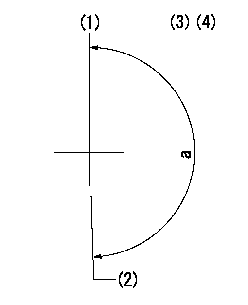
(1)Pump vertical direction
(2)Position of "Z" mark at the No 1 cylinder's beginning of injection (governor side)
(3)B.T.D.C.: aa (set timing)
(4)-
----------
aa=8deg
----------
a=(180deg)
----------
aa=8deg
----------
a=(180deg)
Information:
Tooling, Test, and Bulk Ground Fill Support Equipment
Diesel Exhaust Fluid (DEF)
Two container sizes of DEF are available through the Cat® dealers in North America. DEF must meet ISO 22241-1 specifications.
Table 1
Tool Part Number Description
350-8733 Diesel Exhaust Fluid 9.5 L (2.5 US gal) bottle
350-8734 Diesel Exhaust Fluid 1378 L (364 US gal) tote
443-0955 Removal Tool DEF filter removal tool Dispensing Equipment
Three different dispensing kits are offered to protect DEF quality. Optional flow meter and coupler are also available.
Table 2
Tool Part Number Description
422-1185 Pump Adapter (DEF DISPENSER) 12 V dispenser unit
423-7843 Pump Adapter (DEF DISPENSER) 110 V dispenser unit
423-7844 Pump Adapter (DEF DISPENSER) 230 V dispenser unit with"smart start"tote base
423-7795 Flow Meter In line DEF flow meter
423-7799 Coupler MicroMatic coupler Dispenser Unit Repair Parts
Table 3
Tool Part Number Description
436-6643 Repair Kit 12 V dispenser unit
436-6646 Diesel Exhaust Fluid Pump 12 V repair group
436-6642 Hose 20'/4'
436-6644 Swivel
436-6645 Repair Kit 1/2 hp pump
436-6647 Nozzle (DIESEL EXHAUST FLUID) Dispensing nozzle Storage and Transportation
Preventing DEF contamination does not stop at the pump. Protect your DEF supply with climate-specific enclosures and transportation tanks.
Table 4
Part Number Description
435-8671 Dispenser Warm-weather enclosure
435-8672 Dispenser Cold-weather enclosure
460-4077 Tank 121 L (32 US gal)
460-4078 Tank 269 L (71 US gal) Fast Fill Vehicle Interface
Illustration 1 g06516654
584-9979 Nozzle As
Table 5
584-9979 Nozzle As
Repair parts for 584-9979 Nozzle As
- 587-3371 Rear Cap
- 587-3372 Handle
- 587-3373 Hose (3/4")
- 587-3374 O-Ring Seal
- 587-3375 Handle (optional)
459-9296 Receiver As (Permanently mounted on vehicle)
For heated DEF hose repair connectors, kits, and instructions , refer to Service Magazine, M0103829, "Repair Kits for Quick Connect Diesel Exhaust Fluid (DEF) Line Fittings Are Now Available for Certain Cat® Machine Engines". Testing Equipment
Test your DEF supply and DEF injector with DEF-specific testing equipment. Complete kits or individual testing components are available for your needs.
Table 6
441-0451 Tool Gp (includes hard case, foam insert, and hardware)
- 441-0454 Container
- 443-7055 Test Kit
- 398-4985 Probe
- 398-4987 Probe
- 398-5080 Lead
- 398-5081 Lead
- 398-5083 Plug
450-1515 Tool Gp (DIESEL EXHAUST FLUID) (includes hard case, foam insert, and hardware)
- 441-0454 Container
- 398-4985 Probe
- 398-4987 Probe
- 398-5080 Lead
- 398-5081 Lead
- 398-5083 Plug
441-0454 Container
443-7055 Test Kit
431-7087 Tool Gp (REFRACTOMETER (DEF))
360-0774 Refractometer
372-5260 Test Lead Tool Group
576-6134 Test Strip
