Information injection-pump assembly
ZEXEL
106961-6022
1069616022
ISUZU
1156025022
1156025022

Rating:
Cross reference number
ZEXEL
106961-6022
1069616022
ISUZU
1156025022
1156025022
Zexel num
Bosch num
Firm num
Name
Calibration Data:
Adjustment conditions
Test oil
1404 Test oil ISO4113 or {SAEJ967d}
1404 Test oil ISO4113 or {SAEJ967d}
Test oil temperature
degC
40
40
45
Nozzle and nozzle holder
105780-8140
Bosch type code
EF8511/9A
Nozzle
105780-0000
Bosch type code
DN12SD12T
Nozzle holder
105780-2080
Bosch type code
EF8511/9
Opening pressure
MPa
17.2
Opening pressure
kgf/cm2
175
Injection pipe
Outer diameter - inner diameter - length (mm) mm 8-3-600
Outer diameter - inner diameter - length (mm) mm 8-3-600
Overflow valve (drive side)
134424-4020
Overflow valve opening pressure (drive side)
kPa
255
221
289
Overflow valve opening pressure (drive side)
kgf/cm2
2.6
2.25
2.95
Overflow valve (governor side)
134424-4020
Overflow valve opening pressure (governor side)
kPa
255
221
289
Overflow valve opening pressure (governor side)
kgf/cm2
2.6
2.25
2.95
Tester oil delivery pressure
kPa
157
157
157
Tester oil delivery pressure
kgf/cm2
1.6
1.6
1.6
Direction of rotation (viewed from drive side)
Right R
Right R
Injection timing adjustment
Direction of rotation (viewed from drive side)
Right R
Right R
Injection order
1-4-9-8-
5-2-11-1
0-3-6-7-
Pre-stroke
mm
4.4
4.37
4.43
Rack position
Point A R=A
Point A R=A
Beginning of injection position
Governor side NO.1
Governor side NO.1
Difference between angles 1
Cal 1-4 deg. 15 14.75 15.25
Cal 1-4 deg. 15 14.75 15.25
Difference between angles 2
Cal 1-9 deg. 60 59.75 60.25
Cal 1-9 deg. 60 59.75 60.25
Difference between angles 3
Cal 1-8 deg. 75 74.75 75.25
Cal 1-8 deg. 75 74.75 75.25
Difference between angles 4
Cal 1-5 deg. 120 119.75 120.25
Cal 1-5 deg. 120 119.75 120.25
Difference between angles 5
Cyl.1-2 deg. 135 134.75 135.25
Cyl.1-2 deg. 135 134.75 135.25
Difference between angles 6
Cal 1-11 deg. 180 179.75 180.25
Cal 1-11 deg. 180 179.75 180.25
Difference between angles 7
Cal 1-10 deg. 195 194.75 195.25
Cal 1-10 deg. 195 194.75 195.25
Difference between angles 8
Cal 1-3 deg. 240 239.75 240.25
Cal 1-3 deg. 240 239.75 240.25
Difference between angles 9
Cal 1-6 deg. 255 254.75 255.25
Cal 1-6 deg. 255 254.75 255.25
Difference between angles 10
Cal 1-7 deg. 300 299.75 300.25
Cal 1-7 deg. 300 299.75 300.25
Difference between angles 11
Cal 1-12 deg. 315 314.75 315.25
Cal 1-12 deg. 315 314.75 315.25
Injection quantity adjustment
Adjusting point
A
Rack position
8.3
Pump speed
r/min
800
800
800
Average injection quantity
mm3/st.
96.1
94.6
97.6
Max. variation between cylinders
%
0
-2
2
Basic
*
Fixing the lever
*
Injection quantity adjustment_02
Adjusting point
B
Rack position
8.6
Pump speed
r/min
500
500
500
Average injection quantity
mm3/st.
96.8
94.8
98.8
Fixing the lever
*
Injection quantity adjustment_03
Adjusting point
C
Rack position
7.9
Pump speed
r/min
1100
1100
1100
Average injection quantity
mm3/st.
101.1
99.1
103.1
Fixing the lever
*
Injection quantity adjustment_04
Adjusting point
D
Rack position
5.2+-0.5
Pump speed
r/min
225
225
225
Average injection quantity
mm3/st.
8.8
7.5
10.1
Max. variation between cylinders
%
0
-13
13
Fixing the rack
*
Test data Ex:
Governor adjustment
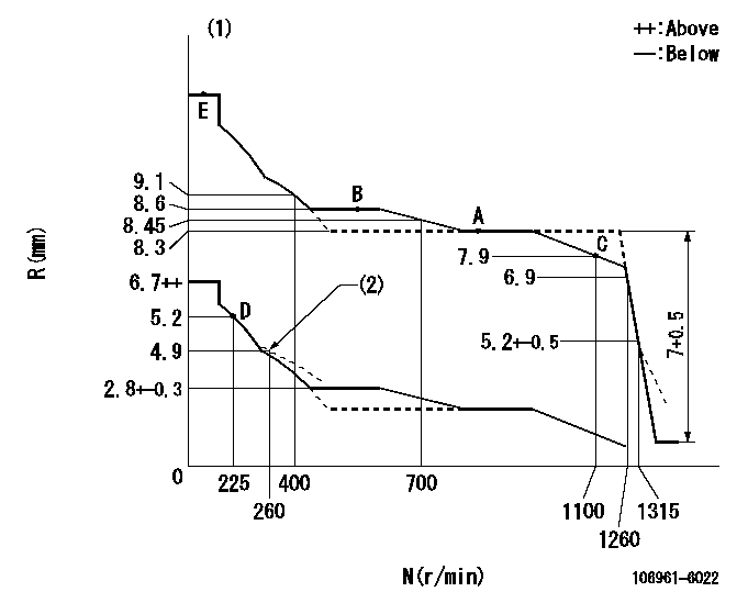
N:Pump speed
R:Rack position (mm)
(1)Tolerance for racks not indicated: +-0.05mm.
(2)Damper spring setting
----------
----------
----------
----------
Timer adjustment

(1)Adjusting range
(2)Step response time
(N): Speed of the pump
(L): Load
(theta) Advance angle
(Srd1) Step response time 1
(Srd2) Step response time 2
1. Adjusting conditions for the variable timer
(1)Adjust the clearance between the pickup and the protrusion to L.
----------
L=1-0.2mm N2=800r/min C2=(7)deg t1=1.5--sec. t2=1.5--sec.
----------
N1=1100++r/min P1=0kPa(0kgf/cm2) P2=392kPa(4kgf/cm2) C1=7+-0.3deg R01=0/4load R02=4/4load
----------
L=1-0.2mm N2=800r/min C2=(7)deg t1=1.5--sec. t2=1.5--sec.
----------
N1=1100++r/min P1=0kPa(0kgf/cm2) P2=392kPa(4kgf/cm2) C1=7+-0.3deg R01=0/4load R02=4/4load
Speed control lever angle

F:Full speed
----------
----------
a=7deg+-5deg
----------
----------
a=7deg+-5deg
0000000901
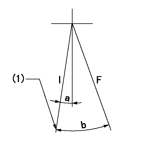
F:Full load
I:Idle
(1)Stopper bolt setting
----------
----------
a=10deg+-5deg b=31deg+-3deg
----------
----------
a=10deg+-5deg b=31deg+-3deg
Stop lever angle
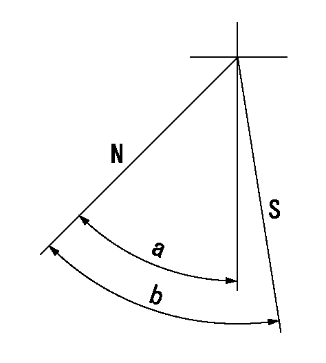
N:Pump normal
S:Stop the pump.
----------
----------
a=60deg+-5deg b=73deg+-5deg
----------
----------
a=60deg+-5deg b=73deg+-5deg
0000001501 RACK SENSOR

V1:Supply voltage
V2f:Full side output voltage
V2i:Idle side output voltage
(A) Black
(B) Yellow
(C) Red
(D) Trimmer
(E): Shaft
(F) Nut
(G) Load lever
1. Load sensor adjustment
(1)Connect as shown in the above diagram and apply supply voltage V1.
(2)Hold the load lever (G) against the full side.
(3)Turn the shaft so that the voltage between (A) and (B) is V2.
(4)Hold the load lever (G) against the idle side.
(5)Adjust (D) so that the voltage between (A) and (B) is V2i.
(6)Repeat the above adjustments.
(7)Tighten the nut (F) at the point satisfying the standards.
(8)Hold the load lever against the full side stopper and the idle side stopper.
(9)At this time, confirm that the full side output voltage is V2f and the idle side output voltage is V2i.
----------
V1=5+-0.02V V2f=0.15+0.03V V2i=2.35-0.03V
----------
----------
V1=5+-0.02V V2f=0.15+0.03V V2i=2.35-0.03V
----------
Timing setting

(1)Pump vertical direction
(2)Position of "Z" mark at the No 1 cylinder's beginning of injection (governor side)
(3)B.T.D.C.: aa (set timing)
(4)-
----------
aa=8deg
----------
a=(180deg)
----------
aa=8deg
----------
a=(180deg)
Information:
Reference for 3500 Series Engines
Troubleshooting, M0080819, "3516E Engine for Tier 4 Final 994K Wheel Loaders".Testing and Adjusting, M0080815, "3516E Engine for Tier 4 Final 994K Wheel Loaders".Disassembly and Assembly, M0092351, "3516E Engines for Caterpillar Built Machines".Procedure
Note: If failed parts need to be shipped back, please cap off the ports using the caps from the new part.
What code are you troubleshooting? ____________________
Follow the correct troubleshooting procedure. Refer to "Reference for C175 Engines" and "Reference for 3500 Series Engines" Sections for correct media number to use.
When troubleshooting procedure requests the DEF quality check, DEF system inspection filter replacement or dosing accuracy, document those results in Table 1, Table 2, Table 3, and Table 4.
Table 1
DEF Quality Results
Step Instruction Completed (Yes/No) Result Comments Units
1 Follow the Testing and Adjusting procedure for "Diesel Exhaust Fluid Quality - Test"
2 DEF Contamination Test (include photo of test strip is possible) Pass/Fail
3 DEF concentration Test % at 20° C (68° F)
Table 2
DEF Tank Vent Line, Breather, and Cap Inspection Results
Step Instruction Completed (Yes/No) Result Comments Units
1 Follow the Testing and Adjusting procedure for "Diesel Exhaust Fluid Quality - Test"
2 DEF Contamination Test (include photo of test strip is possible)
3 DEF concentration Test
4 Remove the breather and inspect at the breather-to-vent line connections if debris is bypassing the breather (take photo)
5 Inspect the DEF tank manual fill cap for damage or debris (take photo)
6 Remove the DEF tank manual fill cap and inspect for damage or debris at the manual fill inlet to the tank (take a photo)
7 Remove the fill neck strainer and inspect for damage or debris (take a photo)
8 Clean or replace the strainer (if necessary) (take a photo)
Table 3
DEF Pump Filters Replaced
Step Instruction Completed (Yes/No) Result Comments Units
1 Prior to removal, inspect the DEF pump suction line fitting and DEF pump filter cap for any damage (take a photo)
2 Replace the DEF pump suction line filter fitting and DEF pump filter on the affected DEF pump. Comment on any notable damage or debris (take a photo of each post removal)
3 Bag, label (pump number in PETU, pump serial number, date removed), and return with pump.
Table 4
Dosing Accuracy Test
Step Instruction Completed (Yes/No) Result Comments Units
1 Follow the Testing and Adjusting, Aftertreatment SCR system Dosing Test.
2 For the pump in question, take a photograph of both DEF injectors, mounts, gaskets, bolts on the SCR inlet prior to removal. Ensure that the picture captures the DEF injector serial number and part number and not which position and which aftertreatment it was installed.
3 For the pump in question, remove both injectors from the SCR inlet.
4 Take a photograph of both DEF injector mounts on the SCR inlet and the tip of both DEF injectors.
5 Install each injector on the beaker.
6 Run the DEF System Dosing Accuracy test through Cat® ET for each injector.
7 Use the beaker to measure the amount of fluid from the dosing test for each injector. ____________________ml
____________________ml
8 Repeat the test for each injector to verify consistency.