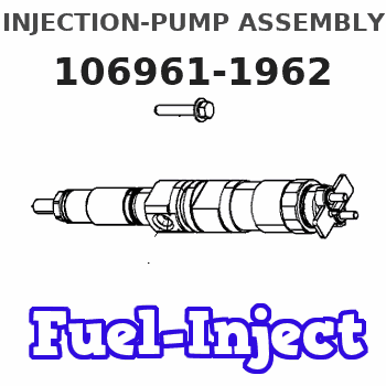
Information injection-pump assembly
ZEXEL
106961-1962
1069611962
ISUZU
1156020774
1156020774
Rating:
Service parts 106961-1962 INJECTION-PUMP ASSEMBLY:
1.
_
6.
COUPLING PLATE
7.
COUPLING PLATE
8.
_
9.
_

11.
Nozzle and Holder
12.
Open Pre:MPa(Kqf/cm2)
19.6(200)
15.
NOZZLE SET
Include in #1:
106961-1962
as INJECTION-PUMP ASSEMBLY
Cross reference number
ZEXEL
106961-1962
1069611962
ISUZU
1156020774
1156020774
Zexel num
Bosch num
Firm num
Name
Calibration Data:
Adjustment conditions
Test oil
1404 Test oil ISO4113 or {SAEJ967d}
1404 Test oil ISO4113 or {SAEJ967d}
Test oil temperature
degC
40
40
45
Nozzle and nozzle holder
105780-8140
Bosch type code
EF8511/9A
Nozzle
105780-0000
Bosch type code
DN12SD12T
Nozzle holder
105780-2080
Bosch type code
EF8511/9
Opening pressure
MPa
17.2
Opening pressure
kgf/cm2
175
Injection pipe
Outer diameter - inner diameter - length (mm) mm 8-3-600
Outer diameter - inner diameter - length (mm) mm 8-3-600
Overflow valve (drive side)
134424-3520
Overflow valve opening pressure (drive side)
kPa
255
221
289
Overflow valve opening pressure (drive side)
kgf/cm2
2.6
2.25
2.95
Overflow valve (governor side)
134424-3520
Overflow valve opening pressure (governor side)
kPa
255
221
289
Overflow valve opening pressure (governor side)
kgf/cm2
2.6
2.25
2.95
Tester oil delivery pressure
kPa
157
157
157
Tester oil delivery pressure
kgf/cm2
1.6
1.6
1.6
Direction of rotation (viewed from drive side)
Right R
Right R
Injection timing adjustment
Direction of rotation (viewed from drive side)
Right R
Right R
Injection order
1-4-9-8-
5-2-11-1
0-3-6-7-
Pre-stroke
mm
4.4
4.37
4.43
Beginning of injection position
Governor side NO.1
Governor side NO.1
Difference between angles 1
Cal 1-4 deg. 15 14.75 15.25
Cal 1-4 deg. 15 14.75 15.25
Difference between angles 2
Cal 1-9 deg. 60 59.75 60.25
Cal 1-9 deg. 60 59.75 60.25
Difference between angles 3
Cal 1-8 deg. 75 74.75 75.25
Cal 1-8 deg. 75 74.75 75.25
Difference between angles 4
Cal 1-5 deg. 120 119.75 120.25
Cal 1-5 deg. 120 119.75 120.25
Difference between angles 5
Cyl.1-2 deg. 135 134.75 135.25
Cyl.1-2 deg. 135 134.75 135.25
Difference between angles 6
Cal 1-11 deg. 180 179.75 180.25
Cal 1-11 deg. 180 179.75 180.25
Difference between angles 7
Cal 1-10 deg. 195 194.75 195.25
Cal 1-10 deg. 195 194.75 195.25
Difference between angles 8
Cal 1-3 deg. 240 239.75 240.25
Cal 1-3 deg. 240 239.75 240.25
Difference between angles 9
Cal 1-6 deg. 255 254.75 255.25
Cal 1-6 deg. 255 254.75 255.25
Difference between angles 10
Cal 1-7 deg. 300 299.75 300.25
Cal 1-7 deg. 300 299.75 300.25
Difference between angles 11
Cal 1-12 deg. 315 314.75 315.25
Cal 1-12 deg. 315 314.75 315.25
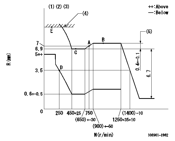
Injection quantity adjustment
Adjusting point
A
Rack position
7
Pump speed
r/min
750
750
750
Average injection quantity
mm3/st.
98
96.5
99.5
Max. variation between cylinders
%
0
-2
2
Basic
*
Fixing the lever
*
Injection quantity adjustment_02
Adjusting point
D
Rack position
3.5+-0.5
Pump speed
r/min
250
250
250
Average injection quantity
mm3/st.
12.5
11.1
13.9
Max. variation between cylinders
%
0
-13
13
Fixing the rack
*
Timer adjustment
Pump speed
r/min
500+-50
Advance angle
deg.
0
0
0
Remarks
Start
Start
Timer adjustment_02
Pump speed
r/min
1250
Advance angle
deg.
5.5
5
6
Remarks
Finish
Finish
Test data Ex:
Governor adjustment
N:Pump speed
R:Rack position (mm)
(1)Lever ratio: RT
(2)Target shim dimension: TH
(3)Damper spring does not operate.
(4)Excess fuel setting for starting: SXL
(5)Rack difference between N = N1 and N = N2
----------
RT=0.8 TH=1.9mm SXL=9.8+0.2mm N1=1250r/min N2=500r/min
----------
----------
RT=0.8 TH=1.9mm SXL=9.8+0.2mm N1=1250r/min N2=500r/min
----------
Speed control lever angle

F:Full speed
----------
----------
a=5deg+-5deg
----------
----------
a=5deg+-5deg
0000000901

F:Full load
I:Idle
(1)Stopper bolt setting
----------
----------
a=10deg+-5deg b=33deg+-3deg
----------
----------
a=10deg+-5deg b=33deg+-3deg
Stop lever angle

N:Pump normal
S:Stop the pump.
----------
----------
a=60deg+-5deg b=73deg+-5deg
----------
----------
a=60deg+-5deg b=73deg+-5deg
Timing setting

(1)Pump vertical direction
(2)Position of "Z" mark at the No 1 cylinder's beginning of injection (governor side)
(3)B.T.D.C.: aa
(4)-
----------
aa=16deg
----------
a=(170deg)
----------
aa=16deg
----------
a=(170deg)
Information:
Introduction
Do not perform any procedure in this Special Instruction until you have read the information and you understand the information.DEF injectors are being replaced in the field and returned to Caterpillar for testing. Results of the testing are finding a large portion of the returned DEF injectors are found to be fault not repeated.This form is to be used and filled out in any case that a DEF injector is being replaced.The DEF injector troubleshooting return form needs to be completed and included within failed part returns documenting what was found that led to DEF injector replacement. Attach the photos of DEF injector tip and mount area along with a Product Status Report to the SIMS claim.References
Table 1
Engine Publication Type Media Number
C7.1 Troubleshooting UENR0668
Testing and Adjusting UENR4467
Disassembly and Assembly UENR4468
C9.3 Troubleshooting UENR0978
Testing and Adjusting UENR3402
Disassembly and Assembly UENR0130
C13 Troubleshooting UENR0955
Testing and Adjusting UENR4302
Disassembly and Assembly UENR0131
C15/C18 Troubleshooting UENR0955
Testing and Adjusting UENR3351
Disassembly and Assembly UENR0132 Procedure
What code are you troubleshooting? __________
Follow the correct troubleshooting procedure. Reference Table 1 for correct media number to use.
When troubleshooting procedure requests the DEF quality check, DEF injector resistance measurement, or Dosing Accuracy Test, document those results in Tables 2, 3, and 4.Tables
Table 2
DEF Quality Results
Step Instruction Completed (Yes/No) Result Comments Units
1 Follow the Testing and Adjusting procedure for "Diesel Exhaust Fluid Quality - Test"
2 DEF Contamination Test Pass / Fail
3 DEF Concentration Test % at 20° C (68° F)
Illustration 1 g06175415
Table 3
Injector Resistance Measurement
Step Instruction Completed (Yes/No) Result Comments Units
1 Turn the keyswitch to the OFF position. Allow 2 minutes to elapse before proceeding.
2 Disconnect the DEF injectors from the applicable harness.
3 Inspect the connector for damage and debris.
4 Measure the temperature of the injector (aluminum body). C
5 Connect two 398-4987 Probes to the DEF injector. The connectors must be used to prevent damage to the DEF injector connector. Reference Illustration 1 for example.
6 Measure the resistance of the DEF injector. Ohms
Table 4
Dosing Accuracy Test
Step Instruction Completed (Yes/No) Result Comments Units
1 Follow the Testing and Adjusting procedure for "Aftertreatment SCR System Dosing - Test"
2 Remove the injector from the DPF outlet.
3 Take a photograph of the DEF injector mount on the DPF outlet and the tip of the DEF injector.
4 Install the injector on the beaker.
5 Run the DEF System Dosing Accuracy test through Cat® Electronic Technician (ET).
6 Use the beaker to measure the amount of fluid from the dosing test. ml
7 Repeat the test to verify consistency. ml
8 Install the injector back onto the DPF outlet.