Information injection-pump assembly
ZEXEL
106961-1913
1069611913
ISUZU
1156021714
1156021714
Rating:
Service parts 106961-1913 INJECTION-PUMP ASSEMBLY:
1.
_
6.
COUPLING PLATE
7.
COUPLING PLATE
8.
_
9.
_
11.
Nozzle and Holder
12.
Open Pre:MPa(Kqf/cm2)
15.7(160)/22.1(225)
15.
NOZZLE SET
Include in #1:
106961-1913
as INJECTION-PUMP ASSEMBLY
Cross reference number
ZEXEL
106961-1913
1069611913
ISUZU
1156021714
1156021714
Zexel num
Bosch num
Firm num
Name
Calibration Data:
Adjustment conditions
Test oil
1404 Test oil ISO4113 or {SAEJ967d}
1404 Test oil ISO4113 or {SAEJ967d}
Test oil temperature
degC
40
40
45
Nozzle and nozzle holder
105780-8140
Bosch type code
EF8511/9A
Nozzle
105780-0000
Bosch type code
DN12SD12T
Nozzle holder
105780-2080
Bosch type code
EF8511/9
Opening pressure
MPa
17.2
Opening pressure
kgf/cm2
175
Injection pipe
Outer diameter - inner diameter - length (mm) mm 8-3-600
Outer diameter - inner diameter - length (mm) mm 8-3-600
Overflow valve (drive side)
134424-3520
Overflow valve opening pressure (drive side)
kPa
255
221
289
Overflow valve opening pressure (drive side)
kgf/cm2
2.6
2.25
2.95
Overflow valve (governor side)
134424-3520
Overflow valve opening pressure (governor side)
kPa
255
221
289
Overflow valve opening pressure (governor side)
kgf/cm2
2.6
2.25
2.95
Tester oil delivery pressure
kPa
157
157
157
Tester oil delivery pressure
kgf/cm2
1.6
1.6
1.6
Direction of rotation (viewed from drive side)
Right R
Right R
Injection timing adjustment
Direction of rotation (viewed from drive side)
Right R
Right R
Injection order
1-4-9-8-
5-2-11-1
0-3-6-7-
Pre-stroke
mm
4
3.97
4.03
Beginning of injection position
Governor side NO.1
Governor side NO.1
Difference between angles 1
Cal 1-4 deg. 15 14.75 15.25
Cal 1-4 deg. 15 14.75 15.25
Difference between angles 2
Cal 1-9 deg. 60 59.75 60.25
Cal 1-9 deg. 60 59.75 60.25
Difference between angles 3
Cal 1-8 deg. 75 74.75 75.25
Cal 1-8 deg. 75 74.75 75.25
Difference between angles 4
Cal 1-5 deg. 120 119.75 120.25
Cal 1-5 deg. 120 119.75 120.25
Difference between angles 5
Cyl.1-2 deg. 135 134.75 135.25
Cyl.1-2 deg. 135 134.75 135.25
Difference between angles 6
Cal 1-11 deg. 180 179.75 180.25
Cal 1-11 deg. 180 179.75 180.25
Difference between angles 7
Cal 1-10 deg. 195 194.75 195.25
Cal 1-10 deg. 195 194.75 195.25
Difference between angles 8
Cal 1-3 deg. 240 239.75 240.25
Cal 1-3 deg. 240 239.75 240.25
Difference between angles 9
Cal 1-6 deg. 255 254.75 255.25
Cal 1-6 deg. 255 254.75 255.25
Difference between angles 10
Cal 1-7 deg. 300 299.75 300.25
Cal 1-7 deg. 300 299.75 300.25
Difference between angles 11
Cal 1-12 deg. 315 314.75 315.25
Cal 1-12 deg. 315 314.75 315.25
Injection quantity adjustment
Adjusting point
A
Rack position
8.1
Pump speed
r/min
700
700
700
Average injection quantity
mm3/st.
85.6
84.1
87.1
Max. variation between cylinders
%
0
-2
2
Basic
*
Fixing the lever
*
Injection quantity adjustment_02
Adjusting point
B
Rack position
7.9+-0.5
Pump speed
r/min
1250
1250
1250
Average injection quantity
mm3/st.
95.9
91.9
99.9
Max. variation between cylinders
%
0
-3
3
Fixing the lever
*
Injection quantity adjustment_03
Adjusting point
C
Rack position
5.4+-0.5
Pump speed
r/min
225
225
225
Average injection quantity
mm3/st.
8
6.6
9.4
Max. variation between cylinders
%
0
-13
13
Fixing the rack
*
Injection quantity adjustment_04
Adjusting point
E
Rack position
-
Pump speed
r/min
150
150
150
Average injection quantity
mm3/st.
137
137
Fixing the lever
*
Remarks
When manual lever is on the boost side
When manual lever is on the boost side
Injection quantity adjustment_05
Adjusting point
F
Rack position
8.1
Pump speed
r/min
1000
1000
1000
Average injection quantity
mm3/st.
94.8
90.8
98.8
Max. variation between cylinders
%
0
-3
3
Fixing the lever
*
Timer adjustment
Pump speed
r/min
750+-50
Advance angle
deg.
0
0
0
Load
1/4
Remarks
Start
Start
Timer adjustment_02
Pump speed
r/min
1000+50
Advance angle
deg.
1
0.5
1
Load
3/4
Timer adjustment_03
Pump speed
r/min
(1075)
Advance angle
deg.
1
0.5
1
Load
4/4
Timer adjustment_04
Pump speed
r/min
1150
Advance angle
deg.
2.5
2.2
2.8
Load
4/4
Timer adjustment_05
Pump speed
r/min
1250
Advance angle
deg.
5
5
6
Load
4/4
Remarks
Finish
Finish
Test data Ex:
Governor adjustment
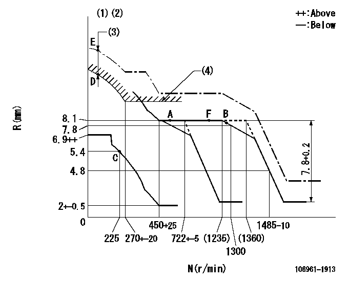
N:Pump speed
R:Rack position (mm)
(1)Supplied with damper spring not set.
(2)Supply solenoid operating voltage DC24V and move the solenoid body so that the excess lever reaches the excess position at the solenoid's maximum stroke.
(3)At excess fuel lever operation: not exceeding EXL
(4)Excess fuel setting for starting: SXL
----------
EXL=2mm SXL=9.2+-0.1mm
----------
----------
EXL=2mm SXL=9.2+-0.1mm
----------
Speed control lever angle
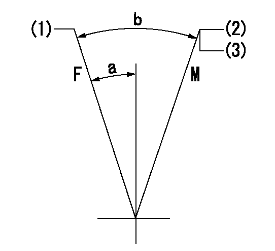
F:Full speed
M:Minimum-maximum speed
(1)Set the pump speed at aa
(2)Set the speed at bb. Set using two nuts.
(3)At delivery
----------
aa=(1360)r/min bb=722+-5r/min
----------
a=9deg+-5deg b=(12deg)+-5deg
----------
aa=(1360)r/min bb=722+-5r/min
----------
a=9deg+-5deg b=(12deg)+-5deg
0000000901

F:Full load
I:Idle
(1)Stopper bolt setting
(2)Use the hole at R = aa
----------
aa=35mm
----------
a=10deg+-5deg b=33deg+-3deg
----------
aa=35mm
----------
a=10deg+-5deg b=33deg+-3deg
Stop lever angle

N:Pump normal
S:Stop the pump.
----------
----------
a=60deg+-5deg b=73deg+-5deg
----------
----------
a=60deg+-5deg b=73deg+-5deg
0000001101

N:Normal
B:When boosted
----------
----------
a=(5deg) b=(24deg)
----------
----------
a=(5deg) b=(24deg)
Timing setting

(1)Pump vertical direction
(2)Position of "Z" mark at the No 1 cylinder's beginning of injection (governor side)
(3)B.T.D.C.: aa
(4)-
----------
aa=12deg
----------
a=(170deg)
----------
aa=12deg
----------
a=(170deg)
Information:
Location of Components
Illustration 1 g06494607
Typical example
(A) DEF tank breather
(B) Heater relay
(C) DEF fast fill tank-mounted valve
(D) Plug heater
(E) Heated supply line
(F) DEF fast fill receiver
(G) DEF tank
Illustration 2 g06494608
(C) DEF fast fill tank-mounted valveThe ground level DEF fill system works much like the ground level fast fuel system. DEF fast fill tank-mounted valve (C) is mounted in DEF tank (G). Fast fill tank-mounted valve (C) has a piston that is normally closed with a spring.
Illustration 3 g06516649
(H) O-Ring seal
(J) Flow In
(K) Flow Out
(L) Back cavityNote: O-Ring seal (H) allows small amount of fluid flow.Note: The main flow through the valve is not shown.Note: During normal flow conditions there is no pressure built up in back cavity (L). Back cavity (L) is essentially "open to atmosphere".When filling, the DEF flow opens the piston, past the diverter shield and a portion flows through an orifice in the piston into the float area.
Illustration 4 g06516652
(L) Back cavity
(M) Rolling diaphragm
(N) O-Ring seal
(P) Drain holeNote: O-Ring seal (N) prevents any flow from back cavity (L).Note: Once the float rises, the pressure in back cavity (L) equals the pressure pushing the front of rolling diaphragm (M). Since the area behind rolling diaphragm (M) is greater than the area in front, along with the spring force, diaphragm (M) is held shut.When the tank level causes the float to rise high enough, the orifice is blocked, causing increased pressure on the piston until valve (C) closes. The increased pressure in the fill line then causes the nozzle attached to the receiver to shut off.The nozzle shuts off when the nozzle sees 172 to 200 kPa (25 to 29 psi) resistance. If pressure is not great enough from the source pump/supply at nozzle, there is not enough pressure built up in line between valve and nozzle to trigger nozzle shut off and DEF exits the breather-overfill.Targeted flow for the DEF supply pump should be 45 L/min (12 US gpm). Excessive flow can lead to premature shut-off of DEF nozzle.DEF tank valve (C), supply line (E), and DEF fast fill receiver (F) are electrically heated based on ambient temperature, battery, and alternator loads controlled through heater relay (B). For heated DEF hose repair kit, refer to Service Magazine, M0103829, "Repair Kits for Quick Connect Diesel Exhaust Fluid (DEF) Line Fittings Are Now Available for Certain Cat® Machine Engines".Note: If receiver (F) and supply line (E) on machine are drained for storage, the system must be refilled via the ground fill connection. The system is refilled to ensure that plug heater (D) in receiver (F) remains submerged in DEF fluid during the heating operation.
Plug heater (D) probe must be submerged at least 80% in DEF fluid to prevent overheating that could lead to plug heater (D) failing.