Information injection-pump assembly
ZEXEL
106961-1879
1069611879
ISUZU
1156021918
1156021918
Rating:
Service parts 106961-1879 INJECTION-PUMP ASSEMBLY:
1.
_
6.
COUPLING PLATE
7.
COUPLING PLATE
8.
_
9.
_
11.
Nozzle and Holder
12.
Open Pre:MPa(Kqf/cm2)
15.7(160)/22.1(225)

15.
NOZZLE SET
Include in #1:
106961-1879
as INJECTION-PUMP ASSEMBLY
Cross reference number
ZEXEL
106961-1879
1069611879
ISUZU
1156021918
1156021918
Zexel num
Bosch num
Firm num
Name
Calibration Data:
Adjustment conditions
Test oil
1404 Test oil ISO4113 or {SAEJ967d}
1404 Test oil ISO4113 or {SAEJ967d}
Test oil temperature
degC
40
40
45
Nozzle and nozzle holder
105780-8140
Bosch type code
EF8511/9A
Nozzle
105780-0000
Bosch type code
DN12SD12T
Nozzle holder
105780-2080
Bosch type code
EF8511/9
Opening pressure
MPa
17.2
Opening pressure
kgf/cm2
175
Injection pipe
Outer diameter - inner diameter - length (mm) mm 8-3-600
Outer diameter - inner diameter - length (mm) mm 8-3-600
Overflow valve (drive side)
134424-3520
Overflow valve opening pressure (drive side)
kPa
255
221
289
Overflow valve opening pressure (drive side)
kgf/cm2
2.6
2.25
2.95
Overflow valve (governor side)
134424-2720
Overflow valve opening pressure (governor side)
kPa
255
221
289
Overflow valve opening pressure (governor side)
kgf/cm2
2.6
2.25
2.95
Tester oil delivery pressure
kPa
157
157
157
Tester oil delivery pressure
kgf/cm2
1.6
1.6
1.6
Direction of rotation (viewed from drive side)
Right R
Right R
Injection timing adjustment
Direction of rotation (viewed from drive side)
Right R
Right R
Injection order
1-8-7-6-
5-4-3-10
-9-2
Pre-stroke
mm
4
3.97
4.03
Beginning of injection position
Governor side NO.1
Governor side NO.1
Difference between angles 1
Cal 1-8 deg. 27 26.75 27.25
Cal 1-8 deg. 27 26.75 27.25
Difference between angles 2
Cal 1-7 deg. 72 71.75 72.25
Cal 1-7 deg. 72 71.75 72.25
Difference between angles 3
Cal 1-6 deg. 99 98.75 99.25
Cal 1-6 deg. 99 98.75 99.25
Difference between angles 4
Cal 1-5 deg. 144 143.75 144.25
Cal 1-5 deg. 144 143.75 144.25
Difference between angles 5
Cal 1-4 deg. 171 170.75 171.25
Cal 1-4 deg. 171 170.75 171.25
Difference between angles 6
Cal 1-3 deg. 216 215.75 216.25
Cal 1-3 deg. 216 215.75 216.25
Difference between angles 7
Cal 1-10 deg. 243 242.75 243.25
Cal 1-10 deg. 243 242.75 243.25
Difference between angles 8
Cal 1-9 deg. 288 287.75 288.25
Cal 1-9 deg. 288 287.75 288.25
Difference between angles 9
Cyl.1-2 deg. 315 314.75 315.25
Cyl.1-2 deg. 315 314.75 315.25
Injection quantity adjustment
Adjusting point
A
Rack position
8.1
Pump speed
r/min
700
700
700
Average injection quantity
mm3/st.
85.6
84.1
87.1
Max. variation between cylinders
%
0
-2
2
Basic
*
Fixing the lever
*
Injection quantity adjustment_02
Adjusting point
B
Rack position
7.9+-0.5
Pump speed
r/min
1250
1250
1250
Average injection quantity
mm3/st.
95.9
91.9
99.9
Max. variation between cylinders
%
0
-3
3
Fixing the lever
*
Injection quantity adjustment_03
Adjusting point
C
Rack position
5.4+-0.5
Pump speed
r/min
225
225
225
Average injection quantity
mm3/st.
8
6.6
9.4
Max. variation between cylinders
%
0
-13
13
Fixing the rack
*
Injection quantity adjustment_04
Adjusting point
E
Rack position
-
Pump speed
r/min
150
150
150
Average injection quantity
mm3/st.
137
137
Fixing the lever
*
Remarks
When manual lever is on the boost side
When manual lever is on the boost side
Injection quantity adjustment_05
Adjusting point
F
Rack position
8.1
Pump speed
r/min
1000
1000
1000
Average injection quantity
mm3/st.
94.8
90.8
98.8
Max. variation between cylinders
%
0
-3
3
Fixing the lever
*
Timer adjustment
Pump speed
r/min
750+50
Advance angle
deg.
0
0
0
Load
1/4
Remarks
Start
Start
Timer adjustment_02
Pump speed
r/min
1000+50
Advance angle
deg.
1
0.5
1
Load
3/4
Timer adjustment_03
Pump speed
r/min
(1075)
Advance angle
deg.
1
0.5
1
Load
4/4
Timer adjustment_04
Pump speed
r/min
1150
Advance angle
deg.
3
2.7
3.3
Load
4/4
Timer adjustment_05
Pump speed
r/min
1250
Advance angle
deg.
6
5.5
6.5
Load
4/4
Remarks
Finish
Finish
Test data Ex:
Governor adjustment
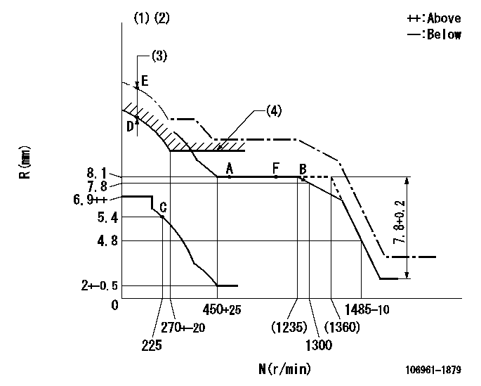
N:Pump speed
R:Rack position (mm)
(1)Supplied with damper spring not set.
(2)Supply solenoid operating voltage DC24V and move the solenoid body so that the excess lever reaches the excess position at the solenoid's maximum stroke.
(3)At excess fuel lever operation: not exceeding EXL
(4)Excess fuel setting for starting: SXL
----------
EXL=2mm SXL=9.2+-0.1mm
----------
----------
EXL=2mm SXL=9.2+-0.1mm
----------
Speed control lever angle

F:Full speed
----------
----------
a=9deg+-5deg
----------
----------
a=9deg+-5deg
0000000901
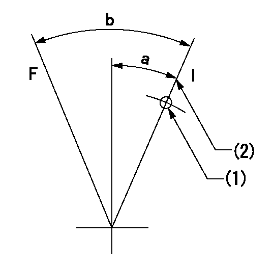
F:Full load
I:Idle
(1)Use the hole at R = aa
(2)Stopper bolt setting
----------
aa=70mm
----------
a=15deg+-5deg b=33deg+-3deg
----------
aa=70mm
----------
a=15deg+-5deg b=33deg+-3deg
Stop lever angle

N:Pump normal
S:Stop the pump.
----------
----------
a=60deg+-5deg b=73deg+-5deg
----------
----------
a=60deg+-5deg b=73deg+-5deg
0000001101
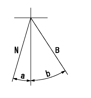
N:Normal
B:When boosted
----------
----------
a=(5deg) b=(24deg)
----------
----------
a=(5deg) b=(24deg)
0000001501 RACK SENSOR

V1:Supply voltage
V2f:Full side output voltage
V2i:Idle side output voltage
(A) Black
(B) Yellow
(C) Red
(D) Trimmer
(E): Shaft
(F) Nut
(G) Load lever
1. Load sensor adjustment
(1)Connect as shown in the above diagram and apply supply voltage V1.
(2)Hold the load lever (G) against the full side.
(3)Turn the shaft so that the voltage between (A) and (B) is V2.
(4)Hold the load lever (G) against the idle side.
(5)Adjust (D) so that the voltage between (A) and (B) is V2i.
(6)Repeat the above adjustments.
(7)Tighten the nut (F) at the point satisfying the standards.
(8)Hold the load lever against the full side stopper and the idle side stopper.
(9)At this time, confirm that the full side output voltage is V2f and the idle side output voltage is V2i.
----------
V1=5+-0.02V V2f=0.15+0.03V V2i=2.35-0.03V
----------
----------
V1=5+-0.02V V2f=0.15+0.03V V2i=2.35-0.03V
----------
0000001601 LEVER
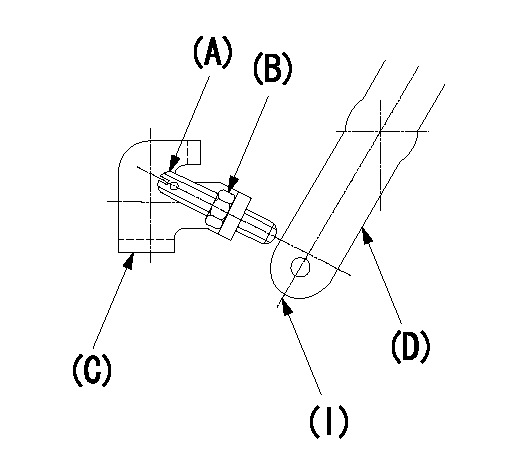
(A) stopper screw
Locknut B
(C) Bracket
(D) Load lever
(I) Idle position
Mechanical autocruise load lever setting procedure
(1)Set the stopper screw after injection pump adjustment.
(2)Set the load lever (D) in the idle position and screw in the stopper screw (A) until it contacts lever (D).
(3)From the above condition, return screw (A) N turns and fix it using the locknut (B).
----------
N=1~1.5
----------
----------
N=1~1.5
----------
Timing setting

(1)Pump vertical direction
(2)Position of "Z" mark at the No 1 cylinder's beginning of injection (governor side)
(3)B.T.D.C.: aa
(4)-
----------
aa=12deg
----------
a=(170deg)
----------
aa=12deg
----------
a=(170deg)
Information:
Retrofit DPF (Diesel Particulate Filter) System
This Retrofit DPF (Diesel Particulate Filter) System must have the following components:
Diesel Particulate Filter (DPF)
Silencer and/or housing
Clamp and gasket
Flow direction label
Engine tagEngine exhaust flows into the Retrofit DPF System reactor housing through the exhaust inlet. Exhaust flows through the DPF.Non-Unidirectional Requirements
(r) Directional Requirements for Diesel Emission Control Strategies
Every diesel emission control strategy must be installed as designed and specified by the manufacturer. For a diesel emission control strategy comprised of multiple exhaust aftertreatment parts, each aftertreatment part must be installed in the proper order relative to the exhaust flow.
Diesel emission control strategies installed between February 19, 2009, and January 1, 2010.
(A) The diesel emission control strategy must indicate the proper direction of exhaust flow. This exhaust flow indicator will allow the end user or installer to see how to install the device properly.
Diesel emission control strategies installed on or after January 1, 2010.
(A) The proper direction for exhaust to flow through the aftertreatment part of the diesel emission control strategy is to be clearly indicated on the outside surface of the aftertreatment part. The exhaust flow indicator consists of an arrow imprinted on or affixed to the aftertreatment part. The indicator arrow is to be clearly visible and durable.
(B) The aftertreatment part must be constructed such that the part can only be installed into the diesel emission control strategy in one unique direction relative to the exhaust flow. The aftertreatment part cannot be installed in the reversed direction.
(C) A diesel emission control strategy not meeting these requirements may be installed after January 1, 2010, if the diesel emission controls strategy: (1) Has a date of manufacture no later than December 31, 2009, (2) Complies with (r)(1) and (r)(2) above and (3) Is installed no later than December 31 2011.
(D) Except for an aftertreatment part that reduces PM through a physical trapping mechanism, such as a diesel particulate filter, the applicant may request that the Executive Officer waives the requirements that an aftertreatment part indicates the flow direction and have unidirectional construction. In reviewing the request, the Executive Officer may consider all relevant information including, but not limited to, the symmetry of the aftertreatment part, potential for impaired performance as a result of different orientations relative to exhaust flow, and interaction with other parts.Diesel Particulate Filter Operation
The Cat DPF is a catalyzed diesel particulate filter that is designed to reduce emissions of particulate (smoke), carbon monoxide (CO) and hydrocarbons (HC), from diesel engines. Carbon monoxide and hydrocarbon reductions are achieved when the exhaust gases interact with the catalyst on the ceramic filter. The catalyst is impregnated on the walls of the ceramic substrate. As the exhaust gases come in contact with the catalyst, a chemical reaction takes place that oxidizes the gases. The oxidation process turns carbon monoxide into carbon dioxide, and hydrocarbons into water and carbon dioxide.Reduction of Emissions
The Cat DPF is a complete product for reducing carbon monoxide, hydrocarbons, and PM. The filter is catalyzed with a precious-metal catalyst. For CO