Information injection-pump assembly
ZEXEL
106961-1588
1069611588
ISUZU
1156032120
1156032120

Rating:
Service parts 106961-1588 INJECTION-PUMP ASSEMBLY:
1.
_
6.
COUPLING PLATE
7.
COUPLING PLATE
8.
_
9.
_
11.
Nozzle and Holder
12.
Open Pre:MPa(Kqf/cm2)
15.7(160)/22.1(225)

15.
NOZZLE SET
Include in #1:
106961-1588
as INJECTION-PUMP ASSEMBLY
Cross reference number
ZEXEL
106961-1588
1069611588
ISUZU
1156032120
1156032120
Zexel num
Bosch num
Firm num
Name
Calibration Data:
Adjustment conditions
Test oil
1404 Test oil ISO4113 or {SAEJ967d}
1404 Test oil ISO4113 or {SAEJ967d}
Test oil temperature
degC
40
40
45
Nozzle and nozzle holder
105780-8140
Bosch type code
EF8511/9A
Nozzle
105780-0000
Bosch type code
DN12SD12T
Nozzle holder
105780-2080
Bosch type code
EF8511/9
Opening pressure
MPa
17.2
Opening pressure
kgf/cm2
175
Injection pipe
Outer diameter - inner diameter - length (mm) mm 8-3-600
Outer diameter - inner diameter - length (mm) mm 8-3-600
Overflow valve (drive side)
134424-3520
Overflow valve opening pressure (drive side)
kPa
255
221
289
Overflow valve opening pressure (drive side)
kgf/cm2
2.6
2.25
2.95
Overflow valve (governor side)
134424-3520
Overflow valve opening pressure (governor side)
kPa
255
221
289
Overflow valve opening pressure (governor side)
kgf/cm2
2.6
2.25
2.95
Tester oil delivery pressure
kPa
157
157
157
Tester oil delivery pressure
kgf/cm2
1.6
1.6
1.6
Direction of rotation (viewed from drive side)
Right R
Right R
Injection timing adjustment
Direction of rotation (viewed from drive side)
Right R
Right R
Injection order
1-4-9-8-
5-2-11-1
0-3-6-7-
Pre-stroke
mm
4.4
4.37
4.43
Beginning of injection position
Governor side NO.1
Governor side NO.1
Difference between angles 1
Cal 1-4 deg. 15 14.75 15.25
Cal 1-4 deg. 15 14.75 15.25
Difference between angles 2
Cal 1-9 deg. 60 59.75 60.25
Cal 1-9 deg. 60 59.75 60.25
Difference between angles 3
Cal 1-8 deg. 75 74.75 75.25
Cal 1-8 deg. 75 74.75 75.25
Difference between angles 4
Cal 1-5 deg. 120 119.75 120.25
Cal 1-5 deg. 120 119.75 120.25
Difference between angles 5
Cyl.1-2 deg. 135 134.75 135.25
Cyl.1-2 deg. 135 134.75 135.25
Difference between angles 6
Cal 1-11 deg. 180 179.75 180.25
Cal 1-11 deg. 180 179.75 180.25
Difference between angles 7
Cal 1-10 deg. 195 194.75 195.25
Cal 1-10 deg. 195 194.75 195.25
Difference between angles 8
Cal 1-3 deg. 240 239.75 240.25
Cal 1-3 deg. 240 239.75 240.25
Difference between angles 9
Cal 1-6 deg. 255 254.75 255.25
Cal 1-6 deg. 255 254.75 255.25
Difference between angles 10
Cal 1-7 deg. 300 299.75 300.25
Cal 1-7 deg. 300 299.75 300.25
Difference between angles 11
Cal 1-12 deg. 315 314.75 315.25
Cal 1-12 deg. 315 314.75 315.25
Injection quantity adjustment
Adjusting point
A
Rack position
7.9
Pump speed
r/min
800
800
800
Average injection quantity
mm3/st.
87.4
85.9
88.9
Max. variation between cylinders
%
0
-2
2
Basic
*
Fixing the lever
*
Injection quantity adjustment_02
Adjusting point
C
Rack position
7.9+-0.5
Pump speed
r/min
1150
1150
1150
Average injection quantity
mm3/st.
94.5
90.5
98.5
Max. variation between cylinders
%
0
-3
3
Fixing the lever
*
Injection quantity adjustment_03
Adjusting point
D
Rack position
5.2+-0.5
Pump speed
r/min
225
225
225
Average injection quantity
mm3/st.
8
6.6
9.4
Max. variation between cylinders
%
0
-13
13
Fixing the rack
*
Injection quantity adjustment_04
Adjusting point
F
Rack position
-
Pump speed
r/min
150
150
150
Average injection quantity
mm3/st.
137
137
Fixing the lever
*
Remarks
When manual lever is on the boost side
When manual lever is on the boost side
Test data Ex:
Governor adjustment

N:Pump speed
R:Rack position (mm)
(1)Tolerance for racks not indicated: +-0.05mm.
(2)Supplied with torque spring not set.
(3)Supplied with damper spring not set.
(4)Supply solenoid operating voltage DC24V and move the solenoid body so that the excess lever reaches the excess position at the solenoid's maximum stroke.
(5)At excess fuel lever operation: not exceeding EXL
(6)Excess fuel setting for starting: SXL (N = N1)
----------
EXL=2mm SXL=9+-0.1mm N1=320r/min
----------
----------
EXL=2mm SXL=9+-0.1mm N1=320r/min
----------
Timer adjustment

(1)Adjusting range
(2)Step response time
(N): Speed of the pump
(L): Load
(theta) Advance angle
(Srd1) Step response time 1
(Srd2) Step response time 2
1. Adjusting conditions for the variable timer
(1)Adjust the clearance between the pickup and the protrusion to L.
----------
L=1-0.2mm N2=800r/min C2=(7)deg t1=1.5--sec. t2=1.5--sec.
----------
N1=950++r/min P1=0kPa(0kgf/cm2) P2=392kPa(4kgf/cm2) C1=7+-0.3deg R01=0/4load R02=4/4load
----------
L=1-0.2mm N2=800r/min C2=(7)deg t1=1.5--sec. t2=1.5--sec.
----------
N1=950++r/min P1=0kPa(0kgf/cm2) P2=392kPa(4kgf/cm2) C1=7+-0.3deg R01=0/4load R02=4/4load
Speed control lever angle

F:Full speed
----------
----------
a=6deg+-5deg
----------
----------
a=6deg+-5deg
0000000901
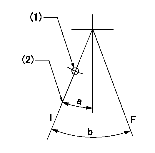
F:Full load
I:Idle
(1)Use the hole at R = aa
(2)Stopper bolt setting
----------
aa=35mm
----------
a=10deg+-5deg b=33deg+-3deg
----------
aa=35mm
----------
a=10deg+-5deg b=33deg+-3deg
Stop lever angle

N:Pump normal
S:Stop the pump.
----------
----------
a=60deg+-5deg b=73deg+-5deg
----------
----------
a=60deg+-5deg b=73deg+-5deg
0000001101

N:Normal
B:When boosted
----------
----------
a=(5deg) b=(24deg)
----------
----------
a=(5deg) b=(24deg)
0000001501 RACK SENSOR

V1:Supply voltage
V2f:Full side output voltage
V2i:Idle side output voltage
(A) Black
(B) Yellow
(C) Red
(D) Trimmer
(E): Shaft
(F) Nut
(G) Load lever
1. Load sensor adjustment
(1)Connect as shown in the above diagram and apply supply voltage V1.
(2)Hold the load lever (G) against the full side.
(3)Turn the shaft so that the voltage between (A) and (B) is V2.
(4)Hold the load lever (G) against the idle side.
(5)Adjust (D) so that the voltage between (A) and (B) is V2i.
(6)Repeat the above adjustments.
(7)Tighten the nut (F) at the point satisfying the standards.
(8)Hold the load lever against the full side stopper and the idle side stopper.
(9)At this time, confirm that the full side output voltage is V2f and the idle side output voltage is V2i.
----------
V1=5+-0.02V V2f=0.15+0.03V V2i=2.35-0.03V
----------
----------
V1=5+-0.02V V2f=0.15+0.03V V2i=2.35-0.03V
----------
Timing setting

(1)Pump vertical direction
(2)Position of "Z" mark at the No 1 cylinder's beginning of injection (governor side)
(3)B.T.D.C.: aa
(4)-
----------
aa=12deg
----------
a=(170deg)
----------
aa=12deg
----------
a=(170deg)
Information:
Communicating with the Wireless Communication Adapter
Table 23 lists the optional hardware that is needed in order to connect Cat ET by using a wireless connection.
Table 23
Optional Hardware for the Use of Cat ET
Part Number Description
N/A Personal Computer (PC)
261-3363 (1) Wireless Communication Adapter Gp
( 1 ) Refer to Tool Operating Manual, "Using the 261-3363 Wireless Communication Adapter Gp " for information that is related to the installation and the configuration.
Illustration 81 g01297379
(1) Personal computer (PC) (7) 261-4867 Card (PCMCIA) (8) 239-9955 Communication Radio Gp (9) 259-3183 Data Link Cable As Note: Items (7), (8), and (9) are part of the 261-3363 Wireless Communication Adapter Gp .Use the following procedure in order to connect the wireless communication adapter for use with Cat ET.
Remove the electrical power from the ECM.
Ensure that the computer has been correctly configured for the 261-4867 Card (PCMCIA). Verify that the PC card is installed in the computer PCI expansion slot.
Connect cable (9) between communication radio (8) and the service tool connector.
Restore the electrical power to the ECM. If Cat ET and the communication radio do not communicate with the ECM, refer to troubleshooting without a diagnostic code Troubleshooting, "Electronic Service Tool Will Not Communicate with ECM".Starting System
The EUI system requires that the crankshaft rotate at a minimum of 70 rpm. The engine starting system must be able to supply the air pressure and flow to the starting motor in order to start the engine. The vane type starting motors may be replaced with turbine type starting motors.If the existing starting system does not meet the 70 rpm requirement, the starting motors must be replaced with turbine type starting motors. Refer to Table 24 for a list of part numbers for the recommended turbine type starting motors for 3600 Engines. For a dual starting motor application, two of the motor group part number must be ordered.Air lines to the starting motors must be modified for the turbine starters. A lubricating device is not required for the turbine type starting motors. Any lubricating device must be removed. The air lines for a single starting motor must have a minimum diameter of 38.1 mm (1.5 inch). Air lines for dual starting motors must have a minimum diameter of 76.2 mm (3.0 inch).
Table 24
Turbine Type Starting Motors for 3600 Engine Applications
Sales Model Standard Rotation Reverse Rotation Quantity
3606 and 3608 269-3839 275-8518 1
3612 (1) 295-6006 295-6007
246-1241 246-4483 2
3616
( 1 ) 3612 Engines can be started by dual starting motors or by a single starting motor. A single starting motor may only be used in cases when minimal parasitic torque is coupled to the engine during cranking. Dual starters may be required in applications when a 3612 Engine must be started in cold ambient conditions. Cold ambient condition will raise the viscosity of the