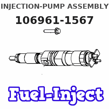
Information injection-pump assembly
ZEXEL
106961-1567
1069611567
ISUZU
1156017319
1156017319
Rating:
Service parts 106961-1567 INJECTION-PUMP ASSEMBLY:
1.
_
6.
COUPLING PLATE
7.
COUPLING PLATE
8.
_
9.
_
11.
Nozzle and Holder
1-15300-163-2
12.
Open Pre:MPa(Kqf/cm2)
15.7{160}/22.1{225}

15.
NOZZLE SET
Include in #1:
106961-1567
as INJECTION-PUMP ASSEMBLY
Cross reference number
ZEXEL
106961-1567
1069611567
ISUZU
1156017319
1156017319
Zexel num
Bosch num
Firm num
Name
Calibration Data:
Adjustment conditions
Test oil
1404 Test oil ISO4113 or {SAEJ967d}
1404 Test oil ISO4113 or {SAEJ967d}
Test oil temperature
degC
40
40
45
Nozzle and nozzle holder
105780-8140
Bosch type code
EF8511/9A
Nozzle
105780-0000
Bosch type code
DN12SD12T
Nozzle holder
105780-2080
Bosch type code
EF8511/9
Opening pressure
MPa
17.2
Opening pressure
kgf/cm2
175
Injection pipe
Outer diameter - inner diameter - length (mm) mm 8-3-600
Outer diameter - inner diameter - length (mm) mm 8-3-600
Overflow valve (drive side)
134424-3520
Overflow valve opening pressure (drive side)
kPa
255
221
289
Overflow valve opening pressure (drive side)
kgf/cm2
2.6
2.25
2.95
Overflow valve (governor side)
134424-3520
Overflow valve opening pressure (governor side)
kPa
255
221
289
Overflow valve opening pressure (governor side)
kgf/cm2
2.6
2.25
2.95
Tester oil delivery pressure
kPa
157
157
157
Tester oil delivery pressure
kgf/cm2
1.6
1.6
1.6
Direction of rotation (viewed from drive side)
Right R
Right R
Injection timing adjustment
Direction of rotation (viewed from drive side)
Right R
Right R
Injection order
1-4-9-8-
5-2-11-1
0-3-6-7-
Pre-stroke
mm
4
3.97
4.03
Beginning of injection position
Governor side NO.1
Governor side NO.1
Difference between angles 1
Cal 1-4 deg. 15 14.75 15.25
Cal 1-4 deg. 15 14.75 15.25
Difference between angles 2
Cal 1-9 deg. 60 59.75 60.25
Cal 1-9 deg. 60 59.75 60.25
Difference between angles 3
Cal 1-8 deg. 75 74.75 75.25
Cal 1-8 deg. 75 74.75 75.25
Difference between angles 4
Cal 1-5 deg. 120 119.75 120.25
Cal 1-5 deg. 120 119.75 120.25
Difference between angles 5
Cyl.1-2 deg. 135 134.75 135.25
Cyl.1-2 deg. 135 134.75 135.25
Difference between angles 6
Cal 1-11 deg. 180 179.75 180.25
Cal 1-11 deg. 180 179.75 180.25
Difference between angles 7
Cal 1-10 deg. 195 194.75 195.25
Cal 1-10 deg. 195 194.75 195.25
Difference between angles 8
Cal 1-3 deg. 240 239.75 240.25
Cal 1-3 deg. 240 239.75 240.25
Difference between angles 9
Cal 1-6 deg. 255 254.75 255.25
Cal 1-6 deg. 255 254.75 255.25
Difference between angles 10
Cal 1-7 deg. 300 299.75 300.25
Cal 1-7 deg. 300 299.75 300.25
Difference between angles 11
Cal 1-12 deg. 315 314.75 315.25
Cal 1-12 deg. 315 314.75 315.25
Injection quantity adjustment
Adjusting point
B
Rack position
8.1
Pump speed
r/min
700
700
700
Average injection quantity
mm3/st.
85.6
84.1
87.1
Max. variation between cylinders
%
0
-2
2
Basic
*
Fixing the lever
*
Injection quantity adjustment_02
Adjusting point
C
Rack position
7.9+-0.5
Pump speed
r/min
1250
1250
1250
Average injection quantity
mm3/st.
95.9
91.9
99.9
Max. variation between cylinders
%
0
-3
3
Fixing the lever
*
Injection quantity adjustment_03
Adjusting point
D
Rack position
5.4+-0.5
Pump speed
r/min
225
225
225
Average injection quantity
mm3/st.
8
6.6
9.4
Max. variation between cylinders
%
0
-13
13
Fixing the rack
*
Injection quantity adjustment_04
Adjusting point
F
Rack position
-
Pump speed
r/min
150
150
150
Average injection quantity
mm3/st.
137
137
Fixing the lever
*
Remarks
When manual lever is on the boost side
When manual lever is on the boost side
Injection quantity adjustment_05
Adjusting point
G
Rack position
8.1
Pump speed
r/min
1000
1000
1000
Average injection quantity
mm3/st.
94.8
90.8
98.8
Max. variation between cylinders
%
0
-3
3
Fixing the lever
*
Timer adjustment
Pump speed
r/min
750+50
Advance angle
deg.
0
0
0
Load
1/4
Remarks
Start
Start
Timer adjustment_02
Pump speed
r/min
1000+50
Advance angle
deg.
1
0.5
1
Load
3/4
Timer adjustment_03
Pump speed
r/min
(1075)
Advance angle
deg.
1
0.5
1
Load
4/4
Timer adjustment_04
Pump speed
r/min
1150
Advance angle
deg.
2.5
2.2
2.8
Load
4/4
Timer adjustment_05
Pump speed
r/min
1250
Advance angle
deg.
5
5
6
Load
4/4
Remarks
Finish
Finish
Test data Ex:
Governor adjustment
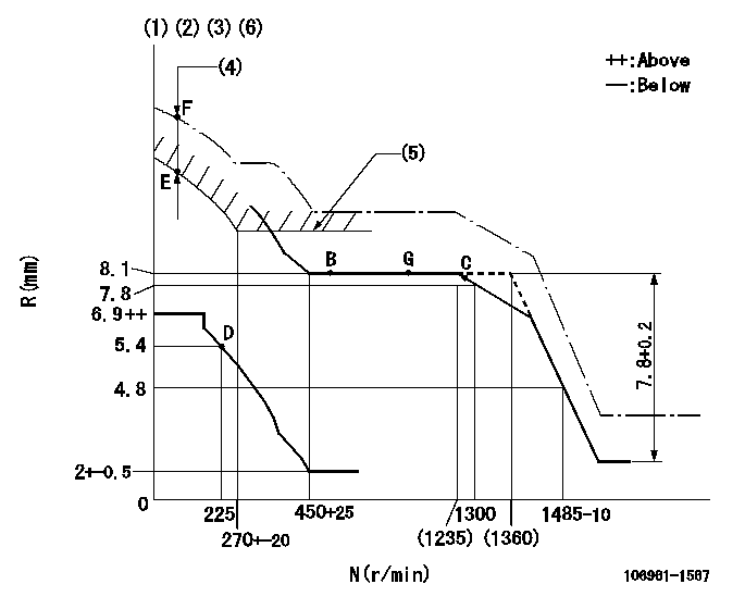
N:Pump speed
R:Rack position (mm)
(1)Lever ratio: RT
(2)Target shim dimension: TH
(3)Supplied with damper spring not set.
(4)At excess fuel lever operation: EXL
(5)Excess fuel setting for starting: SXL
(6)Supply solenoid operating voltage DC24V and move the solenoid body so that the excess lever reaches the excess position at the solenoid's maximum stroke.
----------
RT=0.8 TH=2.3mm EXL=2--mm SXL=9.2+-0.1mm
----------
----------
RT=0.8 TH=2.3mm EXL=2--mm SXL=9.2+-0.1mm
----------
Speed control lever angle

F:Full speed
----------
----------
a=9deg+-5deg
----------
----------
a=9deg+-5deg
0000000901

F:Full load
I:Idle
(1)Stopper bolt setting
(2)Use the hole at R = aa
----------
aa=35mm
----------
a=10deg+-5deg b=33deg+-3deg
----------
aa=35mm
----------
a=10deg+-5deg b=33deg+-3deg
Stop lever angle

N:Pump normal
S:Stop the pump.
----------
----------
a=60deg+-5deg b=73deg+-5deg
----------
----------
a=60deg+-5deg b=73deg+-5deg
0000001101

N:Normal
B:When boosted
----------
----------
a=(5deg) b=(24deg)
----------
----------
a=(5deg) b=(24deg)
Timing setting

(1)Pump vertical direction
(2)Position of "Z" mark at the No 1 cylinder's beginning of injection (governor side)
(3)B.T.D.C.: aa
(4)-
----------
aa=12deg
----------
a=(170deg)
----------
aa=12deg
----------
a=(170deg)
Information:
When all details are filled in, select "Submit".Note: Two labels and a serial number plate will be sent to the dealer address. If two labels are not received, contact Global_Engine_Marking.
Illustration 14 g03159376
Install the new emissions certification film (6), information label (7), and serial number plate on the cylinder block according to the installation instructions received with the labels and plate.Note: Destroy the old emissions certification film and serial number plate.Operation and Maintenance information
There are several specific messages on this machine. The exact location of the messages and the description of the messages are reviewed in this section. Become familiarized with all messages.Make sure that all of the messages are legible. Clean the messages or replace the messages if you cannot read the words. Replace the illustrations if the illustrations are not legible. When you clean the messages, use a cloth, water, and soap. Do not use solvent, gasoline, or other harsh chemicals to clean the messages. Solvents, gasoline, or harsh chemicals could loosen the adhesive that secures the messages. Loose adhesive will allow the messages to fall.Replace any message that is damaged, or missing. If a message is attached to a part that is replaced, install a message on the replacement part. Any Cat® dealer can provide new messages.
Illustration 15 g03518298
Location of films (1) Engine Oil film (2) Diesel Fuel Requirements filmEngine Oil (1)
This film is located on the engine oil filler tube on the right side of the machine.
Illustration 16 g02448560
Cat® DEO-ULS oils and oils that satisfy the "API CJ-4"and/or "ACEA E9" requirements are required for engines that are equipped with a diesel particulate filter.Diesel Fuel Requirements (2)
This film is located by the fuel filler on the right side of the machine.
Illustration 17 g03619316
Use Ultralow Sulfur Diesel (ULSD) fuel.The Environmental Protection Agency (EPA) defines Ultra-Low Sulfur Diesel (ULSD - S15) as "a diesel fuel with a sulfur content not to exceed 15 parts per million (ppm(mg/kg)) or 0.0015 percent by weight". Engines are equipped with exhaust after-treatment systems are designed to run on ULSD only. Use of LSD or fuels higher than 15 ppm (mg/kg) sulfur in these engines will reduce engine efficiency and engine durability. Damage to the emissions control systems and/or shortened service interval will occur. Failures that result form the use of fuels are not Caterpillar factory defects. Therefore the cost of repairs would not be covered by a Caterpillar warranty.In Europe, ultra low sulfur diesel fuel will have a maximum of 0.0010 percent (10 ppm(mg/kg)) sulfur and is typically referred to as "sulfur-free". This sulfur level is defined in European Standard "EN 590:2004".Lubricant Viscosities - Fluids Recommendations
Engine Oil
Cat® oils have been developed and tested to provide the full performance and life that has been designed and built into Cat® engines.
Illustration 18 g02448560
Cat® DEO-ULS or oils that meet the Cat® ECF-3 specification and the API CJ-4 are required for use in the applications listed below. Cat® DEO-ULS and oils meeting Cat® ECF-3 specification and the API CJ-4 and ACEA E9 oil categories have been developed with limited sulfated ash,