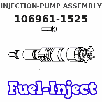
Information injection-pump assembly
ZEXEL
106961-1525
1069611525
ISUZU
1156018357
1156018357
Rating:
Service parts 106961-1525 INJECTION-PUMP ASSEMBLY:
1.
_
6.
COUPLING PLATE
7.
COUPLING PLATE
8.
_
9.
_
11.
Nozzle and Holder
12.
Open Pre:MPa(Kqf/cm2)
15.7(160)/22.1(225)
15.
NOZZLE SET
Include in #1:
106961-1525
as INJECTION-PUMP ASSEMBLY
Cross reference number
ZEXEL
106961-1525
1069611525
ISUZU
1156018357
1156018357
Zexel num
Bosch num
Firm num
Name
Calibration Data:
Adjustment conditions
Test oil
1404 Test oil ISO4113 or {SAEJ967d}
1404 Test oil ISO4113 or {SAEJ967d}
Test oil temperature
degC
40
40
45
Nozzle and nozzle holder
105780-8140
Bosch type code
EF8511/9A
Nozzle
105780-0000
Bosch type code
DN12SD12T
Nozzle holder
105780-2080
Bosch type code
EF8511/9
Opening pressure
MPa
17.2
Opening pressure
kgf/cm2
175
Injection pipe
Outer diameter - inner diameter - length (mm) mm 8-3-600
Outer diameter - inner diameter - length (mm) mm 8-3-600
Overflow valve (drive side)
134424-3520
Overflow valve opening pressure (drive side)
kPa
255
221
289
Overflow valve opening pressure (drive side)
kgf/cm2
2.6
2.25
2.95
Overflow valve (governor side)
134424-2720
Overflow valve opening pressure (governor side)
kPa
255
221
289
Overflow valve opening pressure (governor side)
kgf/cm2
2.6
2.25
2.95
Tester oil delivery pressure
kPa
157
157
157
Tester oil delivery pressure
kgf/cm2
1.6
1.6
1.6
Direction of rotation (viewed from drive side)
Right R
Right R
Injection timing adjustment
Direction of rotation (viewed from drive side)
Right R
Right R
Injection order
1-8-7-6-
5-4-3-10
-9-2
Pre-stroke
mm
4.4
4.37
4.43
Beginning of injection position
Governor side NO.1
Governor side NO.1
Difference between angles 1
Cal 1-8 deg. 27 26.75 27.25
Cal 1-8 deg. 27 26.75 27.25
Difference between angles 2
Cal 1-7 deg. 72 71.75 72.25
Cal 1-7 deg. 72 71.75 72.25
Difference between angles 3
Cal 1-6 deg. 99 98.75 99.25
Cal 1-6 deg. 99 98.75 99.25
Difference between angles 4
Cal 1-5 deg. 144 143.75 144.25
Cal 1-5 deg. 144 143.75 144.25
Difference between angles 5
Cal 1-4 deg. 171 170.75 171.25
Cal 1-4 deg. 171 170.75 171.25
Difference between angles 6
Cal 1-3 deg. 216 215.75 216.25
Cal 1-3 deg. 216 215.75 216.25
Difference between angles 7
Cal 1-10 deg. 243 242.75 243.25
Cal 1-10 deg. 243 242.75 243.25
Difference between angles 8
Cal 1-9 deg. 288 287.75 288.25
Cal 1-9 deg. 288 287.75 288.25
Difference between angles 9
Cyl.1-2 deg. 315 314.75 315.25
Cyl.1-2 deg. 315 314.75 315.25
Injection quantity adjustment
Adjusting point
A
Rack position
7.9
Pump speed
r/min
800
800
800
Average injection quantity
mm3/st.
87.4
85.9
88.9
Max. variation between cylinders
%
0
-2
2
Basic
*
Fixing the lever
*
Injection quantity adjustment_02
Adjusting point
C
Rack position
7.9
Pump speed
r/min
1150
1150
1150
Average injection quantity
mm3/st.
94.5
90.5
98.5
Max. variation between cylinders
%
0
-3
3
Fixing the lever
*
Injection quantity adjustment_03
Adjusting point
D
Rack position
5.2+-0.5
Pump speed
r/min
225
225
225
Average injection quantity
mm3/st.
8
6.6
9.4
Max. variation between cylinders
%
0
-13
13
Fixing the rack
*
Injection quantity adjustment_04
Adjusting point
F
Rack position
-
Pump speed
r/min
150
150
150
Average injection quantity
mm3/st.
137
137
Fixing the lever
*
Remarks
When manual lever is on the boost side
When manual lever is on the boost side
Timer adjustment
Pump speed
r/min
-
Advance angle
deg.
0
0
0
Remarks
Measure speed (beginning of operation).
Measure speed (beginning of operation).
Timer adjustment_02
Pump speed
r/min
-
Advance angle
deg.
0.5
0.3
0.8
Remarks
Measure the actual speed.
Measure the actual speed.
Timer adjustment_03
Pump speed
r/min
(950)
Advance angle
deg.
0.5
0.3
0.8
Timer adjustment_04
Pump speed
r/min
1050
Advance angle
deg.
3
2.7
3.3
Timer adjustment_05
Pump speed
r/min
1150
Advance angle
deg.
6
5.5
6.5
Remarks
Finish
Finish
Test data Ex:
Governor adjustment
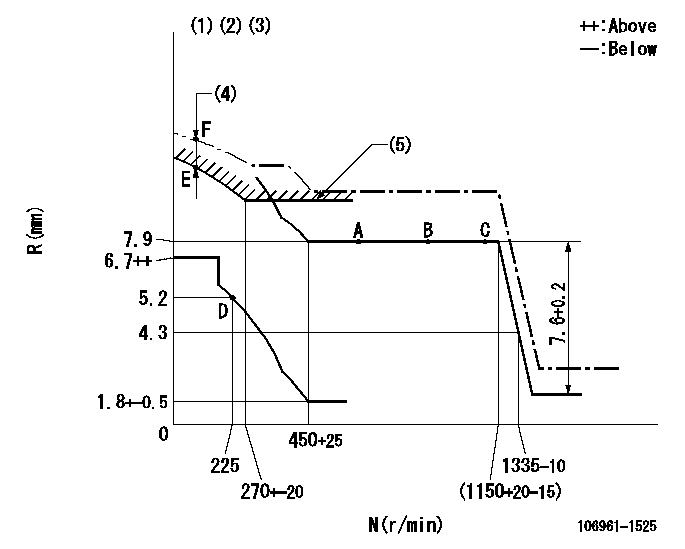
N:Pump speed
R:Rack position (mm)
(1)Supplied with damper spring not set.
(2)Supplied with torque spring not set.
(3)Supply solenoid operating voltage DC24V and move the solenoid body so that the excess lever reaches the excess position at the solenoid's maximum stroke.
(4)At excess fuel lever operation: not exceeding EXL
(5)Excess fuel setting for starting: SXL
----------
EXL=2mm SXL=9+-0.1mm
----------
----------
EXL=2mm SXL=9+-0.1mm
----------
Speed control lever angle

F:Full speed
----------
----------
a=6deg+-5deg
----------
----------
a=6deg+-5deg
0000000901
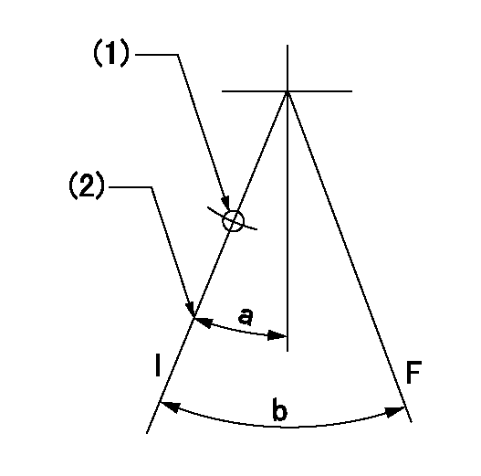
F:Full load
I:Idle
(1)Use the hole at R = aa
(2)Stopper bolt setting
----------
aa=35mm
----------
a=10deg+-5deg b=33deg+-3deg
----------
aa=35mm
----------
a=10deg+-5deg b=33deg+-3deg
Stop lever angle

N:Pump normal
S:Stop the pump.
----------
----------
a=60deg+-5deg b=73deg+-5deg
----------
----------
a=60deg+-5deg b=73deg+-5deg
0000001101
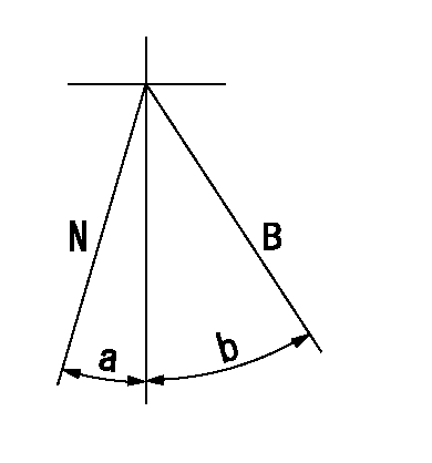
N:Normal
B:When boosted
----------
----------
a=(5deg) b=(24deg)
----------
----------
a=(5deg) b=(24deg)
Timing setting

(1)Pump vertical direction
(2)Position of "Z" mark at the No 1 cylinder's beginning of injection (governor side)
(3)B.T.D.C.: aa
(4)-
----------
aa=12deg
----------
a=(170deg)
----------
aa=12deg
----------
a=(170deg)
Information:
Table 1
Part Number Part Description Qty
378-3187 Diesel Exhaust Fluid Filter Gp 1
423-3251 Connector 1
391-5262 Gasket 1
425-0385 Filter As 1
452-6055 Filter Base As 1
453-1604(1) Diesel Exhaust Fluid Filter Gp 1
453-1605(1) Diesel Exhaust Fluid Filter Gp 1
453-1606(1) Diesel Exhaust Fluid Filter Gp 1
(1) Use Table 2 to choose the correct part that corresponds to the DEF heater
Table 2
DEF Heater Part Number Required DEF Filter
434-3241 453-1604
434-3242 453-1605
434-3243 453-1606 The effective serial numbers for this change are related to the Pump Electronic Tank Unit (PETU) serial numbers and not the machine serial numbers. Table 3 contains the effective serial numbers for the PETU tank. Refer to illustration 1 and illustration 2 for examples of where to locate the PETU serial number.
Illustration 1 g06018843
Typical example
(1) The location of the PETU serial plate.
Illustration 2 g03418749
Typical example
Table 3
PETU Effective Serial Numbers
S/N:PET007086T-UP Refer to Special Instruction, M0066142, A New Diesel Exhaust Fluid Filter is Now Available for C7.1 Engines for installation instructions.